Electric motor drive system for an electric vehicle

a technology of electric motors and electric motors, which is applied in the direction of propulsion by batteries/cells, process and machine control, instruments, etc., can solve the problems of reducing the drivability of the electric vehicle that is run by the output of the electric motor, determining the controllable output voltage of the converter, and reducing controllability. , to achieve the effect of ensuring the drivability of the electric vehicle, suppressing power loss, and improving fuel efficiency

Active Publication Date: 2014-01-28
TOYOTA JIDOSHA KK
View PDF19 Cites 15 Cited by
  • Summary
  • Abstract
  • Description
  • Claims
  • Application Information

AI Technical Summary

Benefits of technology

[0010]The invention thus provides a control over output voltage of a converter that is able to improve fuel efficiency by suppressing power loss in an electric motor drive system of an electric vehicle provided with a converter for performing direct-current voltage conversion and an inverter that converts the output voltage of the converter into alternating-current voltage, while ensuring drivability of the electric vehicle by ensuring torque controllability, according to the state of the vehicle.
[0013]In the aspect described above, the second setting means may set the voltage command value in response to the second direct-current voltage at which power loss, that is in the overall electric motor drive system at the second direct-current voltage corresponding to the voltage command value set by the second setting means, at an operating point of the alternating-current electric motor corresponding to the current operating state is minimized, according to a preset relationship among the operating point of the alternating-current electric motor, the second direct-current voltage, and the power loss.
[0018]In the structure described above, the step-up stopping mode selecting means may set the voltage command value to the first target voltage when the step-up necessity determining mean determines that the step-up operation is not necessary.
[0023]These aspects make it possible to improve fuel efficiency by suppressing power loss in an electric motor drive system of an electric vehicle provided with a converter for performing direct-current voltage conversion and an inverter that converts the output voltage of the converter into alternating-current voltage, while ensuring drivability of the electric vehicle by ensuring torque controllability, by setting the output voltage of the converter appropriately according to the state of the vehicle.

Problems solved by technology

With this kind of an electric motor drive system, determining how to set the controllable output voltage of the converter, i.e., the input side voltage of the inverter, becomes an issue.
However, if a control structure is used that changes the converter output voltage frequently in order to match the actual modulation factor with the modulation factor target value, as described in JP-A-2006-311768, drivability of the electric vehicle that is run by the output of the electric motor may decrease due to reduced controllability of the output torque of the electric motor.
Alternatively, power loss may end up increasing due to the voltage conversion operation of the converter changing frequently.
However, with rectangular wave voltage control, the torque controllability of the electric motor is lower than it is with sine wave PWM control, so if priority is given only to reducing system loss, i.e., improving fuel efficiency, drivability of the electric vehicle may decrease due to reduced torque response.

Method used


Image

  • Electric motor drive system for an electric vehicle
  • Electric motor drive system for an electric vehicle
  • Electric motor drive system for an electric vehicle

Examples


Embodiment Construction

[0035]An example embodiment of the present invention will be described in greater detail below with reference to the accompanying drawings. Incidentally, like or corresponding parts will be denoted by like reference characters and descriptions of those parts will generally not be repeated.

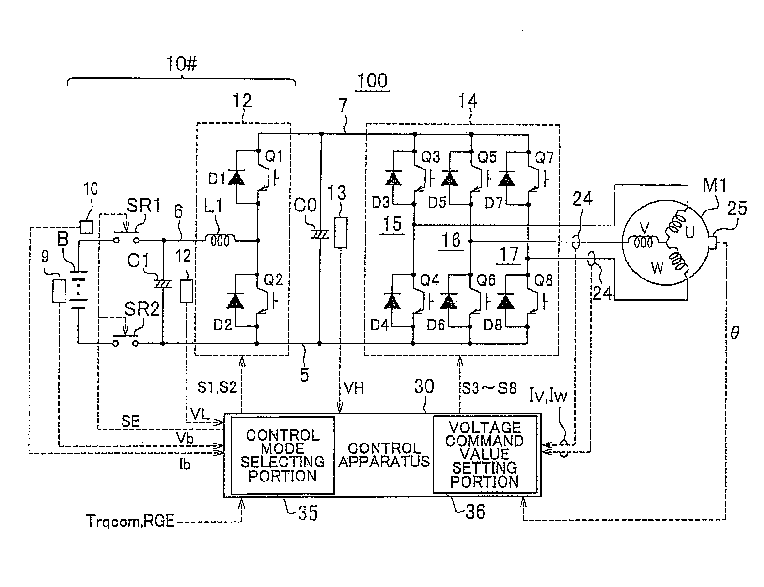
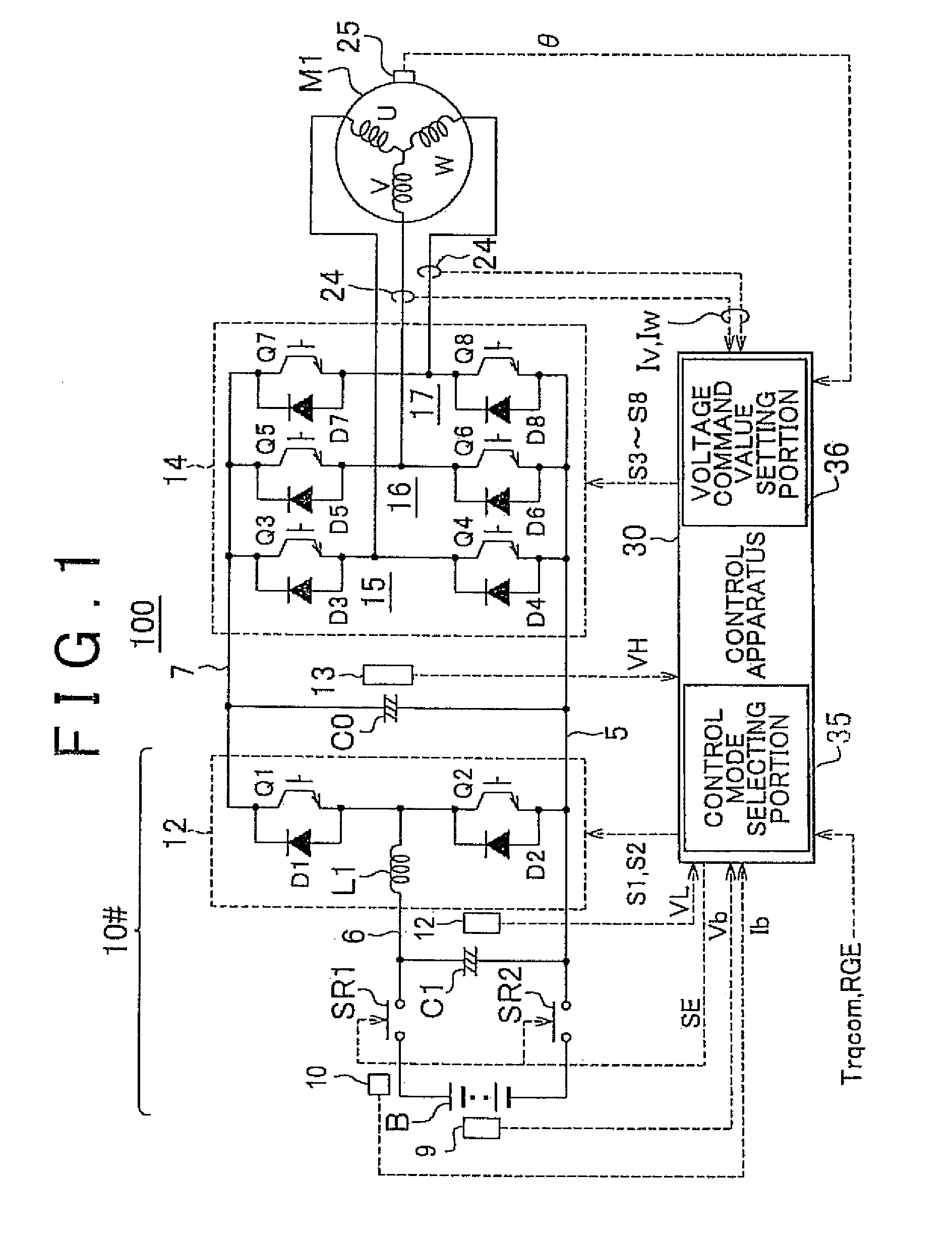
[0036](Overall structure of the electric motor control) FIG. 1 is a diagram of the overall structure of an electric motor drive system according to an example embodiment of the invention.

[0037]As shown in FIG. 1, the electric motor drive system 100 includes a direct-current voltage generating portion (hereinafter simply referred to as “DC voltage generating portion”) 10#, a smoothing capacitor C0, an inverter 14, an alternating-current electric motor (hereinafter simply referred to as “AC electric motor”) M1, and a control apparatus 30.

[0038]The AC electric motor M1 is a driving motor for generating torque used to drive driving wheels of a vehicle powered partially or entirely by electricity (i.e.,...


PUM


Abstract

In an electric motor drive system for an electric vehicle that includes a converter for performing direct-current voltage conversion and an inverter that converts the output voltage of the converter into alternating-current voltage, a control apparatus makes a required torque response determination to determine whether the electric vehicle is in a state in which high torque response is needed. Furthermore, in a drivability priority mode in which high torque response is needed, the control apparatus sets a voltage command value for the converter in a range where sine wave PWM control can be applied. On the other hand, in a fuel efficiency priority mode in which high torque response is not needed, the control apparatus sets the voltage command value for the converter such that power loss in the overall electric motor drive system is minimized, based on the operating state of an alternating-current electric motor.

Description

CROSS-REFERENCE TO RELATED APPLICATIONS[0001]This application is the U.S. National Phase of PCT / lB2010 / 001811 filed Jul. 23, 2010, which claims priority of Japanese Patent Application 2009-206805 filed Sep. 8, 2009.BACKGROUND OF THE INVENTION[0002]1. Field of the Invention[0003]The invention relates to an electric motor drive system for an electric vehicle, and more particularly, a system that drives and controls an alternating-current electric motor by converting direct-current voltage that has been variably controlled by a converter into alternating-current voltage by an inverter.[0004]2. Description of the Related Art[0005]A system that drives and controls a three-phase alternating-current electric motor by converting direct-current voltage (DC voltage) into alternating-current voltage (AC voltage) with an inverter is in general use. With this kind of electric motor drive system, the motor current is typically controlled according to pulse width modulation (PWM) control based on ...

Claims


Application Information

Patent Timeline
Patent Type & Authority Patents(United States)
IPC IPC(8): B60L11/10B60L50/14
CPCB60L11/1803Y02T10/70B60L2240/486B60W10/08H02P21/148B60W20/00H02P27/085H02P21/146B60L2260/12B60W2710/105B60L15/025Y02T10/7005Y02T10/643B60L50/51H02P21/18H02P21/20Y02T10/64Y02T10/72B60L15/02B60W2710/083
Inventor YAMADA, KENJIMORII, AKIYOSHIKAKO, HIROFUMI
Owner TOYOTA JIDOSHA KK
Why Eureka
Try Eureka