Method for determining gear backlash of gear

A technology of transmission mechanism and clearance, applied in transmission control, brake, mechanical equipment, etc., can solve the problems of no clutch, no gear stage, no torsional vibration damper, etc.

Active Publication Date: 2021-04-16
ROBERT BOSCH GMBH
View PDF8 Cites 0 Cited by
  • Summary
  • Abstract
  • Description
  • Claims
  • Application Information

AI Technical Summary

Problems solved by technology

Typically, transmissions consist of fixed ratios without gear s

Method used


Image

  • Method for determining gear backlash of gear
  • Method for determining gear backlash of gear
  • Method for determining gear backlash of gear

Examples


Embodiment Construction

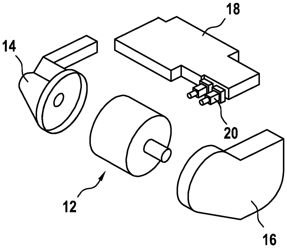
[0026] according to figure 1 From the diagram, a part of the electric axis module 10 can be known. The electric shaft module 10 includes a first housing part 14 and a second housing part 16 . Power electronics 18 , on which electrical connections 20 are formed, are located on both housing parts 14 or 16 .

[0027] figure 2 shows the basis figure 1 An exploded view of the electric axis module 10 shown in . by figure 2 The view from FIG. 1 shows that the electric motor 12 is arranged in the first housing part 14 and in the second housing part 16 . In the assembled state of the two housing parts 14 or 16 , the power electronics 18 is accommodated on the two housing parts together with the electrical connections 20 formed thereon.

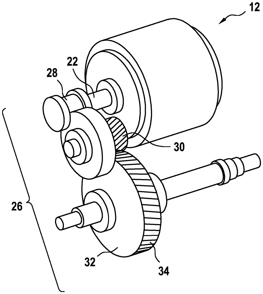
[0028] From image 3 A motor 12 is known in the middle, and a transmission mechanism 24 is driven by an output device 22 of the motor. according to image 3 In the diagram shown, the transmission 24 is a spur gear stage (Stirnradstufe) 26 . ...


PUM


Abstract

The invention relates to a method for determining the transmission mechanism backlash (40) of a transmission mechanism (24) which is coupled to an electric machine (12) of a vehicle which has at least one electric machine (12). According to the method, at least the following steps are carried out: a) detecting the rotational speed of the at least one electric machine (12) during a driving intervention (80) and detecting rotational speed fluctuations produced therefrom; b) evaluating a high-frequency vibration (60) which is generated as a result of the transmission mechanism (24) reaching a lower stop (54) in delay phases (56) and reaching an upper stop (50) when reversing the rotational direction in acceleration phases (58); c) filtering out high-frequency components from the high-frequency vibration (60) according to step b), wherein position information (42), relating to a corresponding rotational angle, from the rotational speed signal is saved in the event the components occur; and d) evaluating the distance between the upper stop (52) and the lower stop (54) and measuring the transmission mechanism backlash (40) from the difference of the position information (42) between the upper stop (52) and the lower stop (54).

Description

technical field [0001] The invention relates to a method for determining a transmission play of a transmission coupled to an electric machine of a vehicle having at least one electric machine. Background technique [0002] DE 10 2015 120 263 A1 relates to a method for determining wear in a device in which a motor moves a load via a transmission, for example a transmission. The motor is assigned a first incremental position sensor and the load is assigned a second incremental position sensor. At a certain load situation, a measured difference between two incremental sensors is determined, wherein the measured difference can be an angular difference. Subsequently, the amplitude of the vibration described by the measured difference is determined and an amplitude function is calculated from the determined amplitude. The amplitude function is compared with the stored characteristic functions to select at least one closest characteristic function from the stored characteristic f...

Claims


Application Information

Patent Timeline
IPC IPC(8): G01M13/021
CPCG01M13/021B60T8/173F16H59/38B60Y2300/207B60Y2300/77G01M13/028G01M13/022F16H57/01F16H2057/018B60W20/17B60L2270/14B60L2270/142G01M13/02
Inventor K·里斯-穆勒
Owner ROBERT BOSCH GMBH
Why Eureka
Try Eureka