
Fuel injection control apparatus and fuel injection control method

a control apparatus and internal combustion engine technology, applied in the direction of electric control, combustion engines, machines/engines, etc., can solve the problems of increasing the amount of hydrocarbons (hc) produced, adversely affecting drivability, and the temperature in the cylinder tends to fall, so as to reduce ensure drivability, and suppress the amount of hc produced

Inactive Publication Date: 2011-01-04
TOYOTA JIDOSHA KK
View PDF16 Cites 6 Cited by
  • Summary
  • Abstract
  • Description
  • Claims
  • Application Information

AI Technical Summary

Benefits of technology

This invention thus provides a fuel injection control apparatus and fuel injection control method for a compression ignition internal combustion engine, which is capable of ensuring drivability while suppressing the amount of HC produced.
Accordingly, the invention provides a fuel injection control apparatus and fuel injection control method for a compression ignition internal combustion engine, which can ensure drivability while suppressing the amount of HC that is produced.

Problems solved by technology

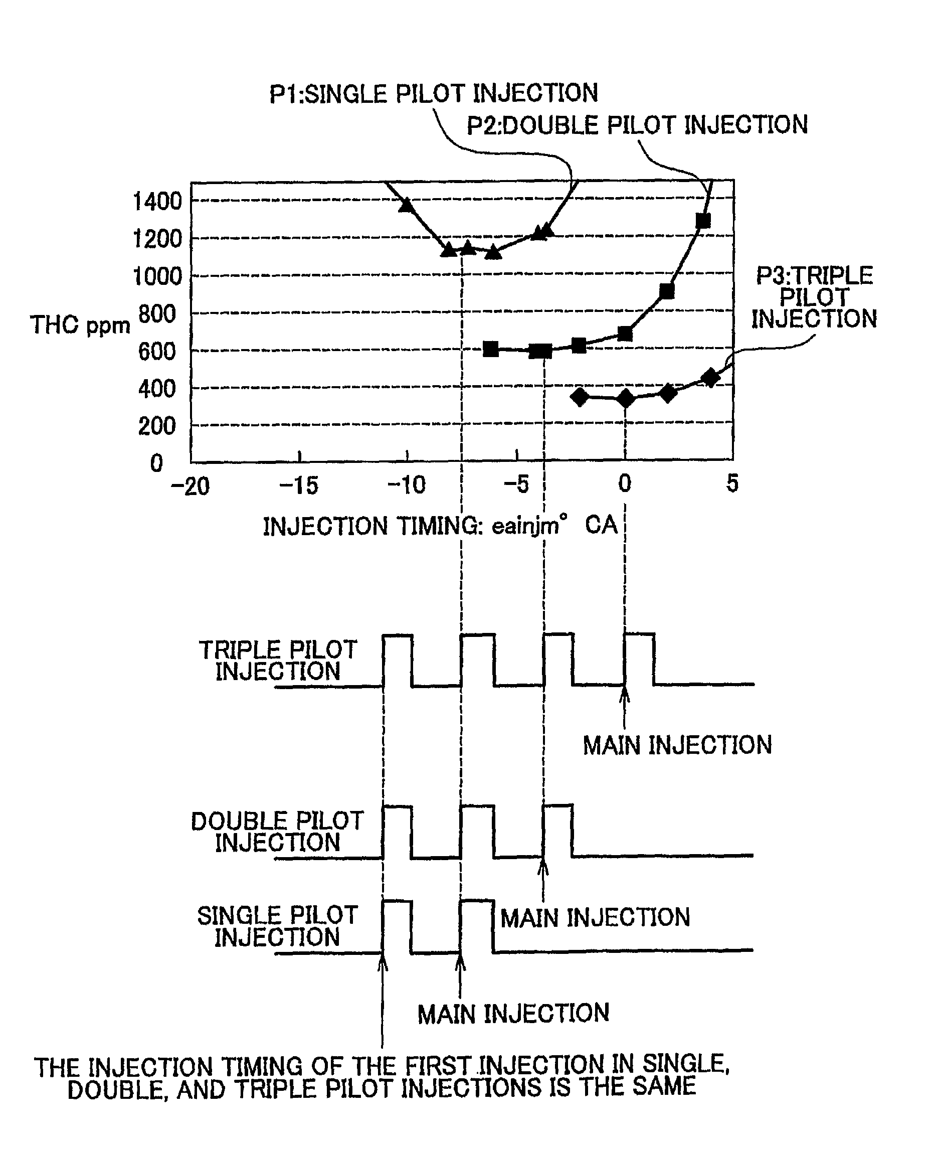
In this kind of a diesel engine, only a small amount of fuel is injected when the engine is operating in the low load region so the temperature in the cylinders tends to fall.
If the temperature in the cylinders (hereinafter also referred to as “cylinder temperature”) falls, combustion may become unstable, leading to an increase in the amount of hydrocarbons (HC) that are produced.
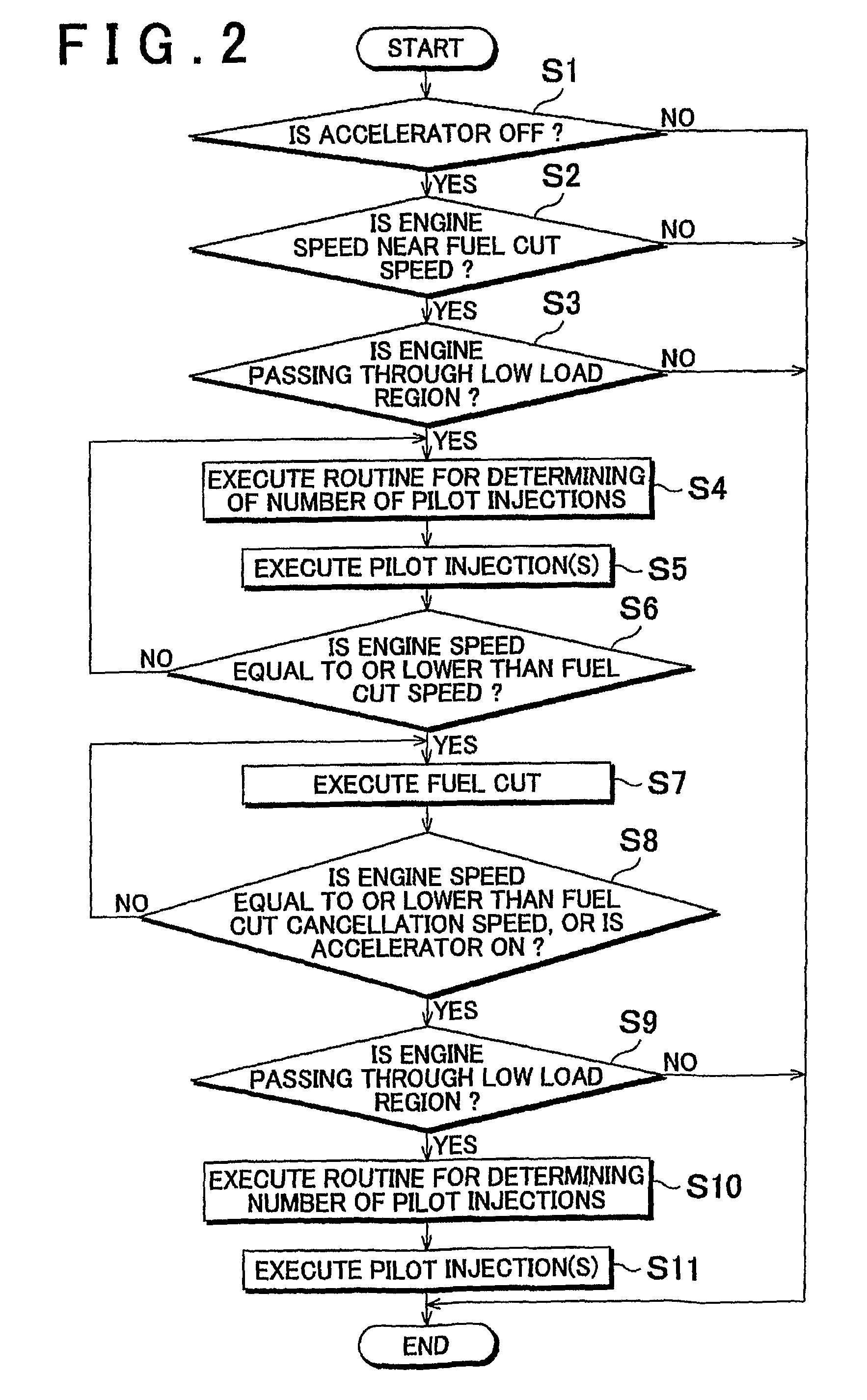
However, when such a pilot injection is performed right after a fuel cut is executed, for example, torque shock may be produced when the operating region of the engine shifts from the low load region to the fuel cut region or from the fuel cut region to the low load region depending on the number of pilot injections, and this torque shock may adversely affect drivability.

Method used


Image

  • Fuel injection control apparatus and fuel injection control method
  • Fuel injection control apparatus and fuel injection control method
  • Fuel injection control apparatus and fuel injection control method

Examples


Embodiment Construction

In the following description and the accompanying drawings, the present invention will be described in greater detail with reference to example embodiments.

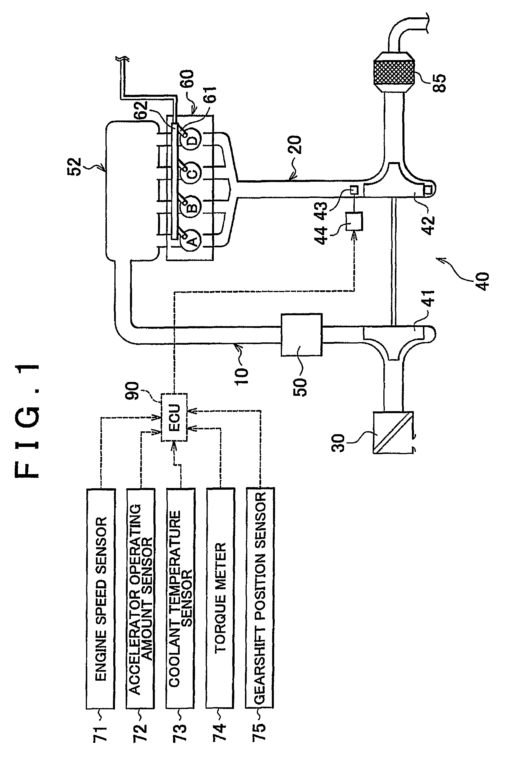
FIG. 1 is a block diagram of an engine system according to a first example embodiment of the invention. The engine system includes an intake passage 10, an exhaust passage 20, an air cleaner 30, a turbocharger 40, an intercooler 50, a surge tank 52, a diesel engine 60, a filter 85, and an ECU (electronic control unit) 90, and the like.

The ECU 90 includes a CPU (Central Processing Unit), ROM (Read Only Memory), and RAM (Random Access Memory) and the like, and controls the operation of various devices. The ECU 90 is also able to execute a routine for determining the number of pilot injections, which will be described later, according to a control program stored in the ROM. Various data obtained during the process of executing the routine for determining the number of pilot injections is temporarily stored in the RAM.

First, intake a...


PUM


Abstract

According to an internal combustion engine fuel injection control apparatus and control method, when an operating region of the engine shifts from a fuel cut region in which no fuel is injected to a low load region in which a small amount of fuel is injected, or visa versa, at least one pilot injection is executed ahead of a main injection in the low load region, and the number of pilot injections is determined according to the engine coolant temperature. This injection control makes it possible to ensure drivability while suppressing the amount of HC produced.

Description

BACKGROUND OF THE INVENTION1. Field of the InventionThe invention relates to a fuel injection control apparatus and a fuel injection control method for a compression ignition internal combustion engine.2. Description of the Related ArtJapanese Patent Application Publication No. 60-017250 (JP-A-60-017250), Japanese Patent Application Publication No. 2001-193463 (JP-A-2001-193463), Japanese Patent Application Publication No. 2004-027939 (JP-A-2004-027939), Japanese Patent Application Publication No. 2006-274969 (JP-A-2006-274969), and Japanese Patent Application Publication No. 11-93735 (JP-A-11-93735) describe a fuel injection control apparatus for a compression ignition internal combustion engine such as a diesel engine, which injects high pressure fuel stored in a common rail a plurality of times into each cylinder during one combustion stroke.In this kind of a diesel engine, only a small amount of fuel is injected when the engine is operating in the low load region so the temperat...

Claims


Application Information

Patent Timeline
Patent Type & Authority Patents(United States)
IPC IPC(8): F02B3/10
CPCF02D41/126F02D41/403Y02T10/44Y02T10/40
Inventor OGURA, SEIJIOHKI, HISASHIKOYAMA, TAKASHI
Owner TOYOTA JIDOSHA KK
Learn More