Switch electric power device

A technology of switching power supply and control power supply, which is applied in the direction of conversion equipment with intermediate conversion to AC

Inactive Publication Date: 2005-07-13
SANKEN ELECTRIC CO LTD
View PDF1 Cites 15 Cited by
  • Summary
  • Abstract
  • Description
  • Claims
  • Application Information

AI Technical Summary

Problems solved by technology

[0030] However, since the power loss of the starting circuit 61 is proportional to the difference between the input voltage Vi and the supply v...

Method used


Image

  • Switch electric power device
  • Switch electric power device
  • Switch electric power device

Examples


no. 1 Embodiment

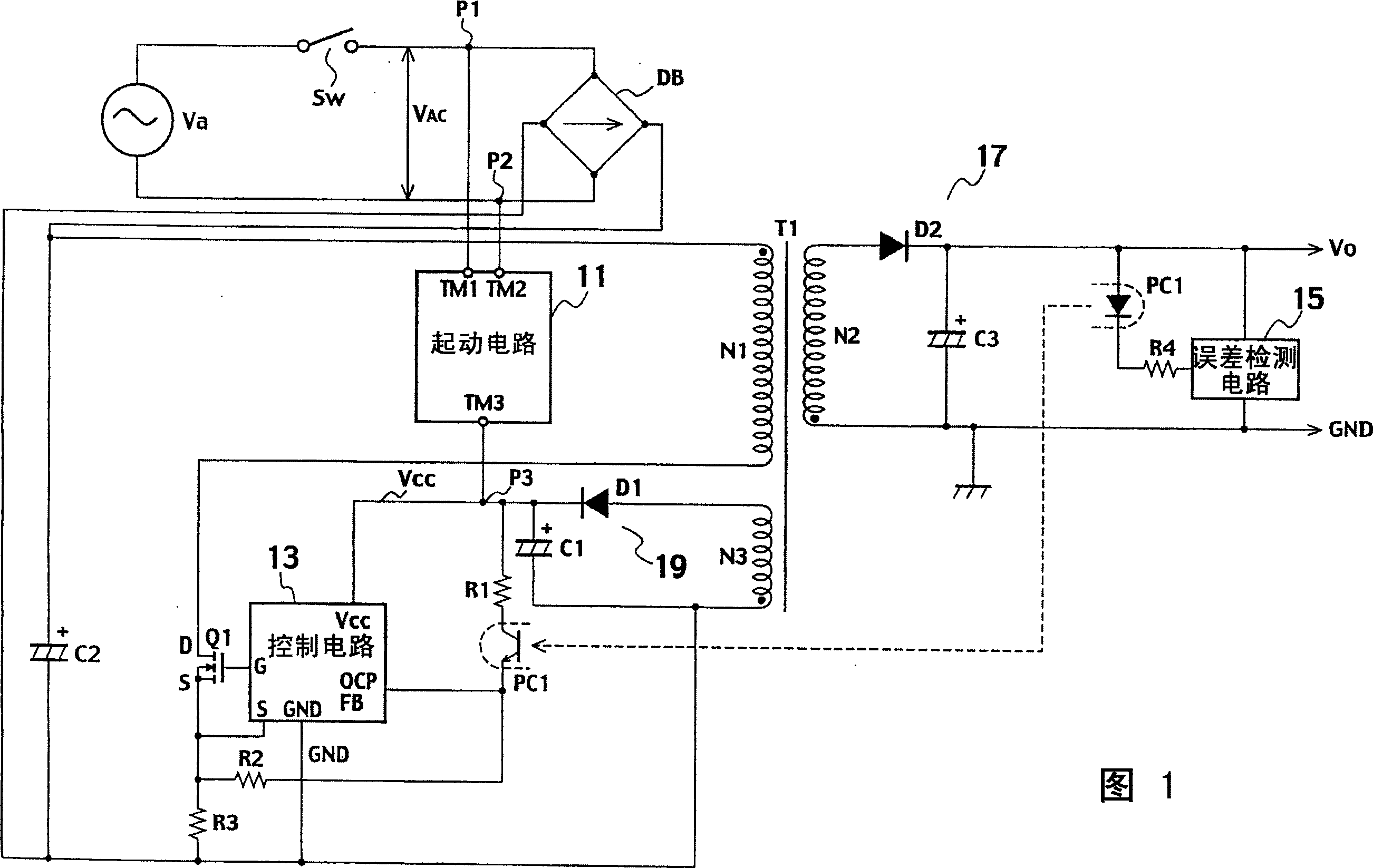
[0053] First, with reference to FIG. 1, the overall configuration of a switching power supply device according to a first embodiment of the present invention will be described.

[0054] In this switching power supply device, for example, a commercial power supply having an AC voltage Va of 100 to 220 V is connected to one terminal of a switch Sw, the other end of the switch Sw is connected to two input terminals of a rectifier circuit DB, and the rectifier circuit DB is connected to The two input terminals are connected to the two input terminals TM1 , TM2 of the starting circuit 11 via connection points P1 , P2 .

[0055] Two output terminals of the rectifier circuit DB are connected to both ends of the capacitor C2, and the primary coil N1 of the transformer T1, the drain of the switching element Q1, and the resistor R3 connected in series are connected in parallel to the capacitor C2.

[0056] The diode D2 and the capacitor C3 connected in series are connected in parallel t...

no. 2 Embodiment

[0119] The overall structure of the switching power supply device of the second embodiment of the present invention is the same as that of the first embodiment. It is the switching power supply device shown in FIG. instruction of.

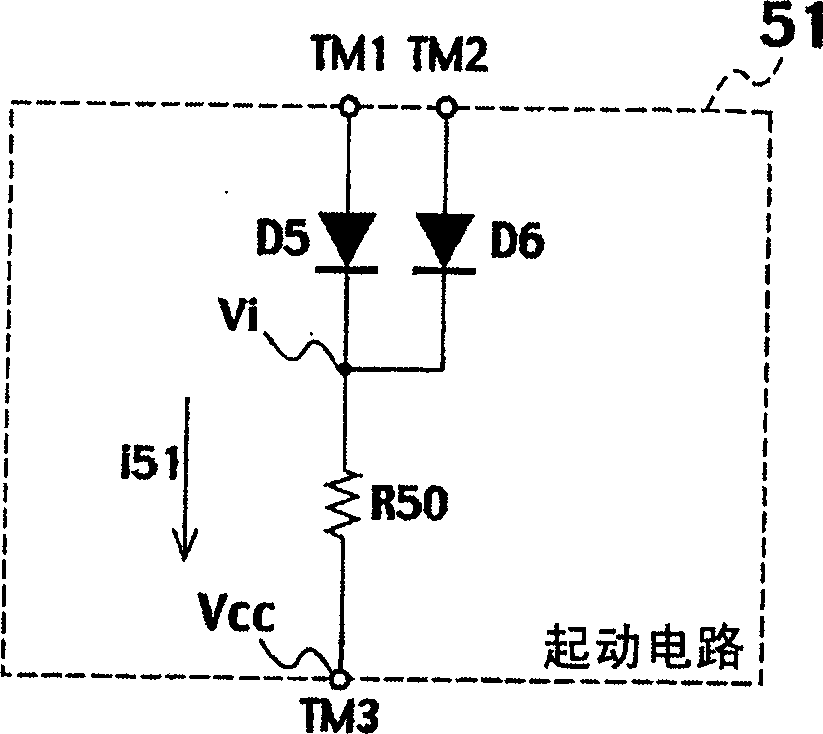
[0120] Second, refer to Figure 13 , the configuration of the starting circuit 31 of the switching power supply device according to the second embodiment of the present invention will be described.

[0121] Such as Figure 13 As shown, the two input terminals TM1 and TM2 of the starting circuit 31 are connected to the two input terminals of the rectification circuit DB through connection points P1 and P2. On the other hand, the output terminal TM3 of the starting circuit 31 is connected to a connection point P3 for supplying the power supply voltage Vcc to the control circuit 13 .

[0122] The starting circuit 31 is composed of an input voltage detection unit 23 that detects an input voltage Vi, and a starting current control unit 35 that contro...


PUM


Abstract

The present invention provides a switching power supply device capable of suppressing power loss in a starting circuit even when an input voltage rises. The input voltage detection part 21 detects the input voltage, and when the peak value of the input AC voltage is above a predetermined value, the transistor Q6 of the starting current control part 25 is turned off, and the current i1 flowing in the starting circuit 21 is reduced, so The conduction angle of the transistor Q6 is narrowed in inverse proportion to the input voltage Vi, and the average value of the current i flowing in the starting circuit 21 is decreased in inverse proportion to the input voltage Vi.

Description

technical field [0001] The invention relates to a starting circuit for starting a switching power supply, in particular to a starting circuit for supplying power to a control circuit for stabilizing an output voltage from an input voltage side. Background technique [0002] A switching power supply is necessary for a control circuit that controls the switching elements to be turned on and off to stabilize the output voltage at a constant voltage. Usually, the control circuit is incorporated into a single unit composed of a circuit structure having a plurality of transistors, etc. chip integrated circuit. [0003] The power supply voltage for operating the integrated circuit chip can be easily obtained, for example, as an auxiliary output voltage of the switching power supply after the switching power supply device has been started, but it must be supplied by the input voltage in other ways at least at the time of starting. , thus using a start-up circuit for starting the in...

Claims


Application Information

Patent Timeline
IPC IPC(8): H02M3/28
Inventor 宇津野瑞木冈部康宽
Owner SANKEN ELECTRIC CO LTD
Why Eureka
Try Eureka