Wireless patient ambulation motion detector and second call system

a motion detector and patient technology, applied in the field of patient ambulation motion detectors, can solve the problems of many false alarms, excessive delay, confusion and consumption of responsibility, etc., and achieve the effect of reducing the shortage of nurses

Inactive Publication Date: 2006-07-04
CALLAWAY JAMES J
View PDF7 Cites 36 Cited by
  • Summary
  • Abstract
  • Description
  • Claims
  • Application Information

AI Technical Summary

Benefits of technology

[0011]Another object of this invention is to provide a wireless motion detector for the prevention of sudden infant death syndrome (SIDS). Adaption of the switching circuit, employing two switches, may be utilized to detect rolling movement, either to the right or the left, as would occur if the infant turns from its back to a face-down position. By detecting the rolling movement, it would help prevent the undesired face-down position.
[0012]A still further object of this invention is to incorporate a second switch in the center of the transmitter case. It can function as a call button and be programmed to send a separate signal, indicating a patient's need for “comfort” care, ie., personal care, etc. Technical care, i.e., discussion of medical problems, medication, etc., would be obtained through the conventional wired call system. The two call systems would divide the responsibility among care givers. Elimination of the demands for the traditional nursing station to service comfort calls could help reduce the nurse shortage. The nurse's station would monitor calls from either system and signals received at the nurse's station could alert the nurse as to the type of patient need. Technical calls are monitored by the wired system. Comfort care and ambulation alert calls are monitored through the wireless monitor-recorder: a constant light indicating an ambulation call and an interrupted light indicating a comfort call.

Problems solved by technology

It is a confining and consuming responsibility.
Devices utilizing only a single mercury switch caused many false alarms, and were a distinct disadvantage.
Oftentimes an excessive delay is encountered when the nursing station attempts to locate and inform the assigned nurse that a given patient is ambulatory.

Method used


Image

  • Wireless patient ambulation motion detector and second call system
  • Wireless patient ambulation motion detector and second call system
  • Wireless patient ambulation motion detector and second call system

Examples


Embodiment Construction

[0023]In describing preferred embodiments of the invention illustrated in the drawings, specific terminology will be resorted to for the sake of clarity. However, the invention is not intended to be limited to the specific terms so selected, and it is to be understood that each specific term includes all technical equivalents which operate in a similar manner to accomplish a similar purpose.

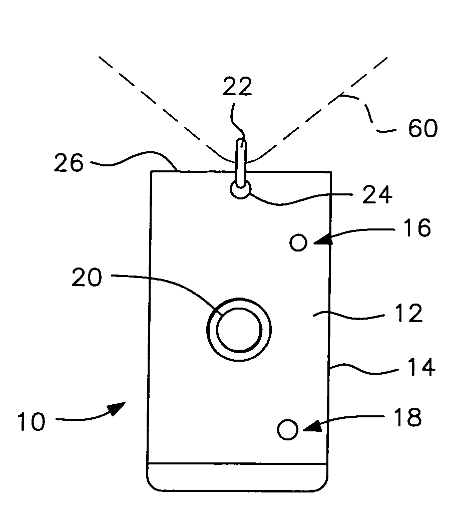
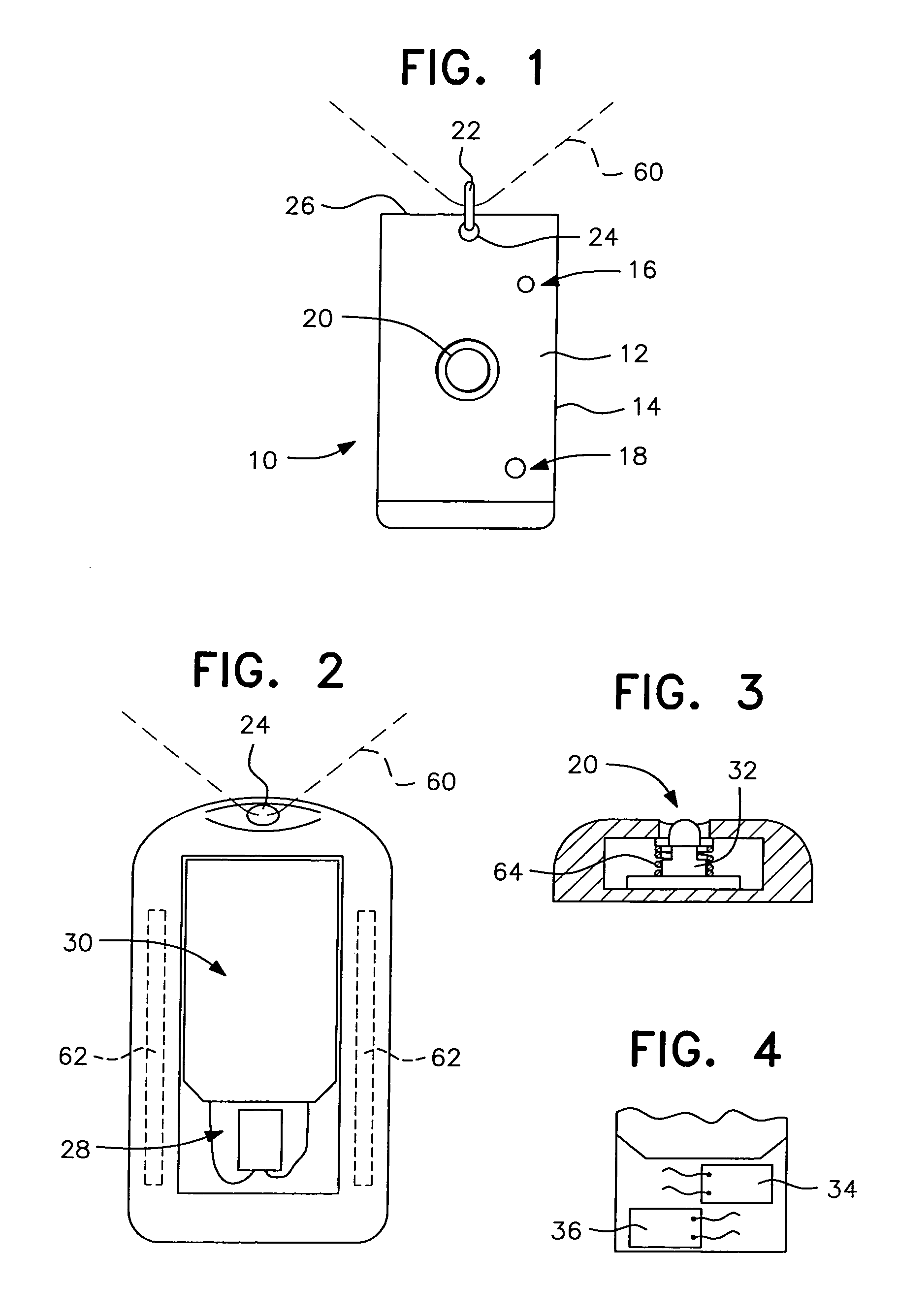
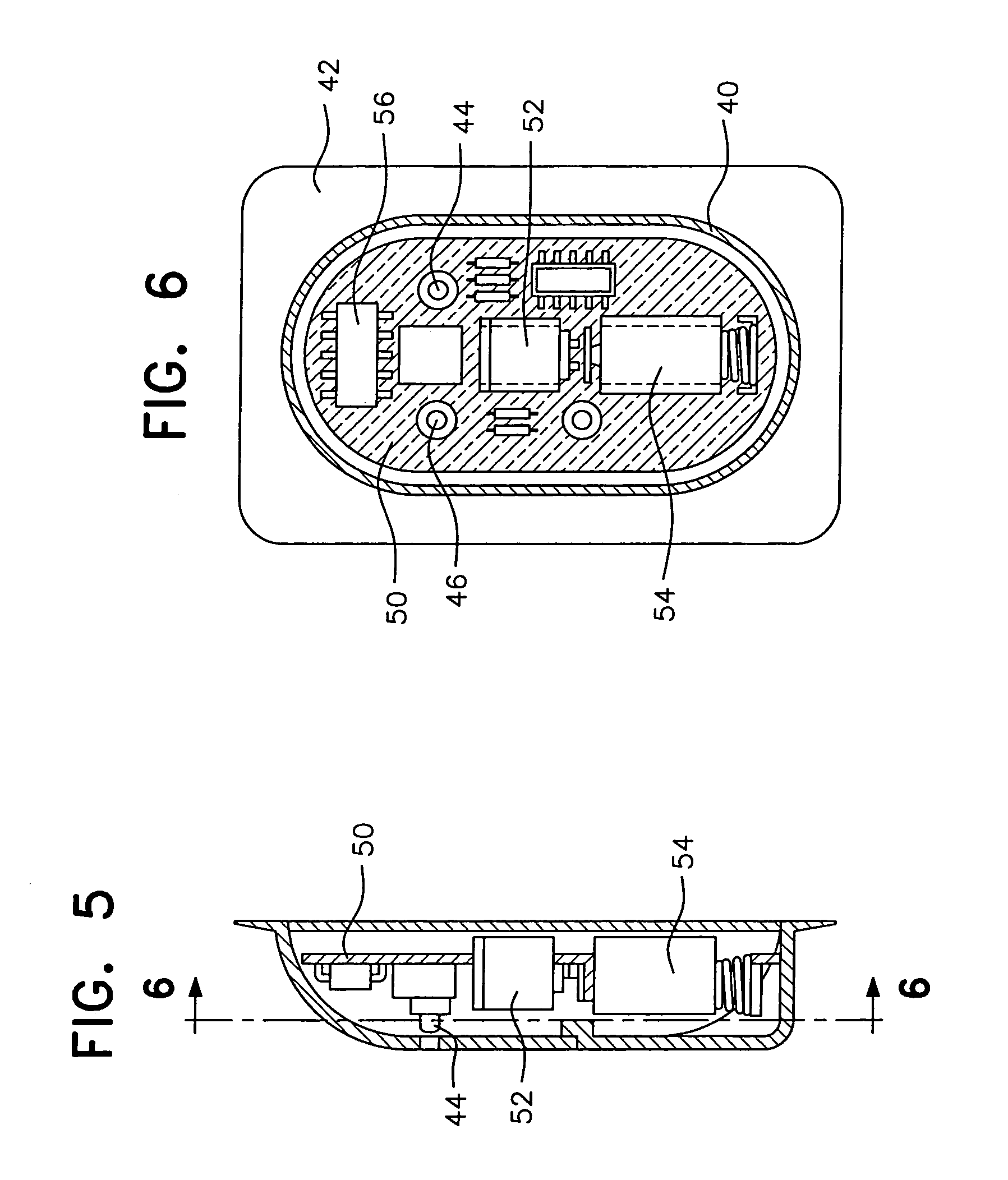
[0024]The wireless patient ambulation motion detector and second call system of this invention consists of three functional components as follows:[0025]1. As illustrated above with reference to my prior patents, a rotary switch capable of detecting when the angle of the patient's body is 85°–90° from the horizontal, the position most often indicative of impending ambulation. All other positions will be ignored thus eliminating false alarms. This switch is intended to alert hospital personnel of a situation which could result in a fall by the patient.[0026]2. A low power wireless transmitter and p...


PUM


Abstract

A patient ambulation motion detector designed to be worn on the body. The detector incorporates a wireless transmitter, a motion sensor switch and a second call switch. It may be enclosed in a plastic case and attached most commonly to the upper anterior chest by a non-allergic double-backed tape.

Description

[0001]This application claims priority from and the benefit of U.S. Provisional Application Ser. No. 60 / 455,573, filed on Mar. 19, 2003, hereby incorporated in its entirety by reference.BACKGROUND OF THE INVENTION[0002]1. Field of the Invention[0003]This invention relates to a patient ambulation motion detector designed for attachment to a person's body. The detector includes a motion sensor switch and a second call switch that activates a low voltage radio frequency transmitter, transmitting a signal to a pager receiver and / or a monitor recorder. The components of the motion detector are preferably encased in a plastic housing which may be attached to the anterior surface of a person's body by a non-allergic, double-backed tape.[0004]2. Discussion of the Related Art[0005]Prevention of falls in acute care facilities, long term care facilities and in the private home is an important part of the care of compromised persons. It is a confining and consuming responsibility. It is often i...

Claims


Application Information

Patent Timeline
Patent Type & Authority Patents(United States)
IPC IPC(8): G08B1/08A61B5/08G08B21/00G08B23/00G08B21/02G08B21/04G08B21/22G08B25/01
CPCG08B21/02G08B25/016G08B21/22G08B21/0446
Inventor CALLAWAY, JAMES J.
Owner CALLAWAY JAMES J
Why Eureka
Try Eureka