Antenna apparatus

a technology of antenna arrays and antennas, applied in the field of antenna apparatuses, can solve the problems of low assembling efficiency and degrade assembling efficiency, and achieve the effect of simple structure and high efficiency

Inactive Publication Date: 2006-07-04
DX ANTENNA CO LTD
View PDF7 Cites 13 Cited by
  • Summary
  • Abstract
  • Description
  • Claims
  • Application Information

AI Technical Summary

Benefits of technology

[0009]A directivity adjusting means is disposed in the casing. The directivity adjusting means adjusts the phases and levels of reception signals from the first through fourth dipole antennas. (In this specification, a reception signal means a signal resulting from receiving a radio wave by an antenna.) The directivity adjusting means makes it possible to change combined directivities of the first through fourth dipole antennas as desired.
[0011]The first phase adjusting means adjusts the phases of reception signals from the first and second dipole antennas and combines them into a combined signal. In this case, the reception signal from one of the first and second dipole antennas may be adjusted to have the same phase as the reception signal from the other of the first and second dipole antennas, or the reception signals from both dipole antennas may be adjusted to have the same phase. The phase adjustment and combining makes it possible to orient the combined directivity of the first and second dipole antennas to a selected one of a first direction along the second imaginary line and a second direction opposite to the first direction. The second phase adjusting means adjusts the phases of reception signals from the third and fourth dipole antennas and combines them into a combined signal. In this case, the reception signal from one of the third and fourth dipole antennas may be adjusted to have the same phase as the reception signal from the other of the third and fourth dipole antennas, or the reception signals from both dipole antennas may be adjusted to have the same phase. The phase adjustment and combining makes it possible to orient the combined directivity of the third and fourth dipole antennas to a selected one of a third direction along the first imaginary line and a fourth direction opposite to the third direction.
[0012]The level adjusting and combining means adjusts the levels of output signals of the first and second phase adjusting means and combines them, which makes it possible to change the combined directivities of the first through fourth dipole antennas as desired. The first and second phase adjusting means and the level adjusting and combining means are disposed within the casing.
[0013]Since the first through fourth antennas are dipole antennas of relatively simple structure and are arranged in the same plane, they can be assembled in the casing with high efficiency. In addition, since the first through fourth dipole antennas are arranged in line symmetry with respect to the first through fourth imaginary lines, combined directivities of the first through fourth antennas can be in symmetry, with the respective imaginary lines being axes of symmetry. Baluns may be used for coupling the reception signals from the first through fourth dipole antennas to the first and second phase adjusting means. Each balun should preferably be at a location on the imaginary line between the two feed points of associated dipole antennas so that it is in line symmetry with respect to that imaginary line. Also, the baluns for the first and second dipole antennas are disposed in line symmetry with respect to the first imaginary line, and the baluns for the third and fourth dipole antenna are disposed in line symmetry with respect to the second imaginary line. This arrangement of the baluns enables the use of connecting lines of the substantially same length for connecting the feed points of the respective dipole antennas, which are in line symmetry with respect to the first through fourth imaginary lines, to the associated baluns, so that the phases of the reception signals supplied to the baluns can match with each other.

Problems solved by technology

Four of such Yagi antennas formed of many components must be housed in a single casing, and, therefore, the assembling efficiency is low.
In addition, two Yagi antennas must be placed in one plane, while remaining two must be placed in a different plane, which further degrades the assembling efficiency.

Method used


Image

  • Antenna apparatus
  • Antenna apparatus
  • Antenna apparatus

Examples


Embodiment Construction

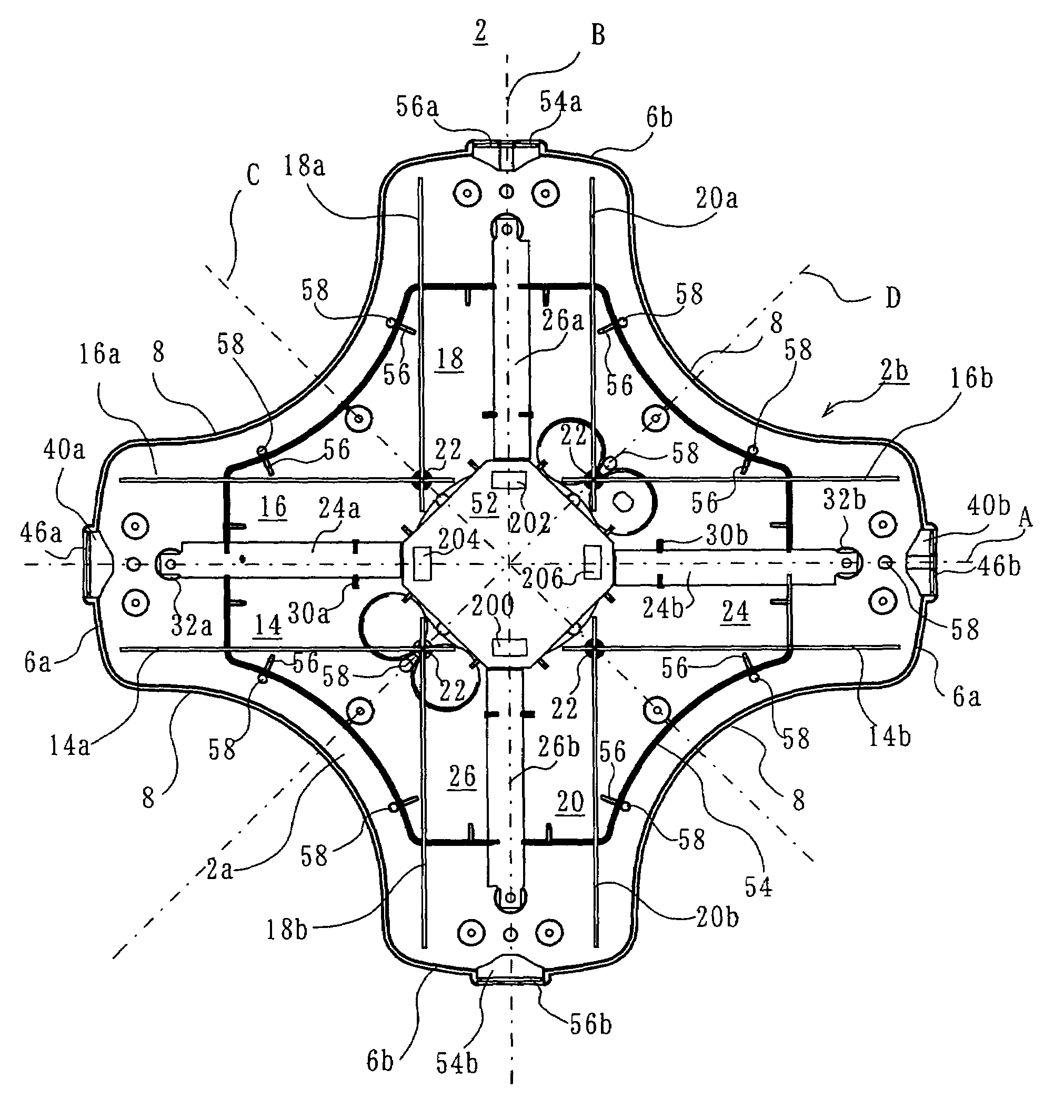
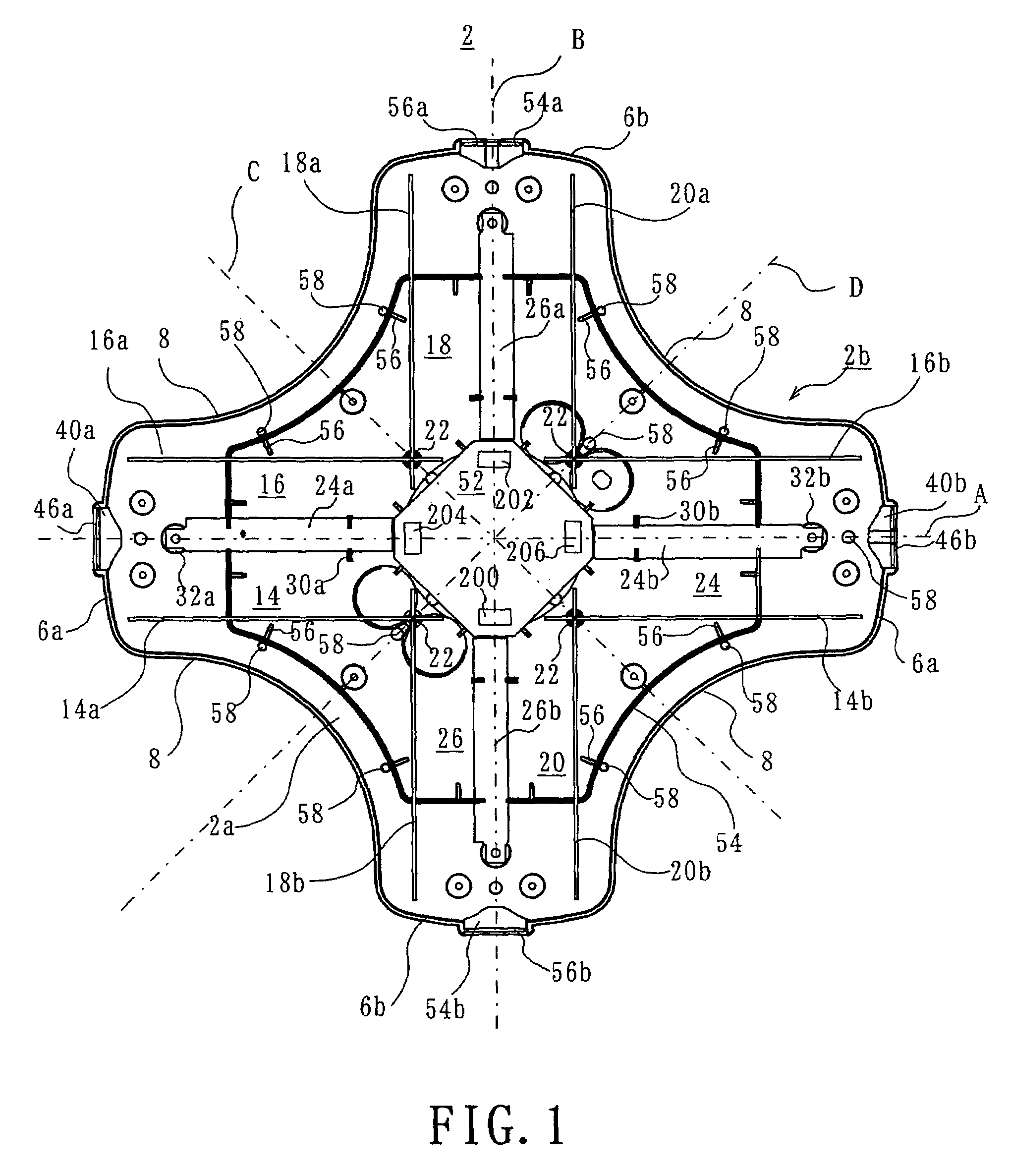
[0026]Referring to FIG. 3, an antenna apparatus according to the present invention includes a casing 1. The casing 1 is formed of a main body 2 and a lid 4. The main body 2 is formed of, for example, a synthetic resin, and has a generally octagonal shape in plan. The inner bottom surface of the casing 1 slopes downward from the peripheral portion toward the center, and is open at one side, e.g. upper side. The opening is closed by the lid 4, which is also octagonal in plan. The lid 4, too, is formed of a synthetic resin, for example, and slopes upward from its peripheral portion toward the center.

[0027]The main body 2 has a bottom wall 2a and a peripheral wall 2b extending along the periphery of the bottom wall 2a, as shown in FIG. 1. As shown in FIGS. 2, 3 and 4, the peripheral wall 2b includes a pair of spaced-apart ends 6a, 6a, and also a pair of spaced-apart ends 6b, 6b. The line connecting the ends 6a and 6a orthogonally intersects the line connecting the ends 6b and 6b. Arcuat...


PUM


Abstract

First, second, third and fourth dipole antennas (14, 16, 18, 20) are disposed in a casing (1). The first through fourth dipole antennas are arranged in the same plane, and are disposed in line symmetry with respect to first through fourth imaginary lines (A, B, C, D) passing through the center of the casing (1) at an angle of 45 degrees between adjacent imaginary lines.

Description

[0001]This invention relates to an antenna apparatus and, more particularly, to an antenna apparatus housed in a casing.BACKGROUND OF THE INVENTION[0002]An example of an antenna apparatus housed in a casing is disclosed in U.S. Pat. No. 6,498,589 patented on Dec. 24, 2002. The antenna apparatus disclosed therein includes a main body having a generally octagonal shape in plan, and a lid or cover closing an opening in the main body. Four Yagi antennas are arranged in the main body. First two of the four Yagi antennas are aligned on a first imaginary straight line passing through the main body, and exhibit directivities oriented in mutually opposite directions along the first imaginary straight line. The remaining, second two Yagi antennas are aligned on a second imaginary straight line extending orthogonal to the first imaginary straight line and exhibit directivities oriented in mutually opposite directions along the second imaginary straight line. The second two Yagi antennas are di...

Claims


Application Information

Patent Timeline
Patent Type & Authority Patents(United States)
IPC IPC(8): H01Q21/00H01Q1/42H01Q21/12
CPCH01Q1/42H01Q9/28H01Q21/29H01Q21/28H01Q21/24
Inventor SHIROSAKA, TOSHIAKITATEKAWA, KIYOTAKAFUJITA, TOSHIO
Owner DX ANTENNA CO LTD
Why Eureka
Try Eureka