Synchronizing video formats with dissimilar timing

a video format and timing technology, applied in the field of synchronizing video formats with dissimilar timing, can solve the problems of dropped video lines, problems in display devices connected to slave machines, and frequency drift in independent timebase between masters

Active Publication Date: 2006-07-04
ORACLE INT CORP
View PDF16 Cites 12 Cited by
  • Summary
  • Abstract
  • Description
  • Claims
  • Application Information

AI Technical Summary

Benefits of technology

[0018]Vertical synchronization may be accomplished by using a Vertical Reset signal, which is not asynchronous since the pixel clock is derived from the timing of the Master. The Frame Reset signal will occur at the same instant in the video frame of the one or more Slaves, and as a result the one or more Slaves will not drop any video lines.

Problems solved by technology

The problem with the Framelock synchronization technique is a potential for frequency drift in the independent timebase between the Master and the one or more Slaves, caused by the independent operation of the local timebase crystals.
These variations can result in dropped video lines if the Master resets a Slave whose video timing has not progressed to the same line as the Master.
The dropped lines can cause problems in display devices connected to the slave machine.
As a result, the Framelock synchronization technique may be insufficient to achieve frame synchronization required by many high-end visualization-simulation and scientific visualization applications.
The problem with the Genlock synchronization technique is that the PLLs used for Genlocking typically require that the video formats of the Master and the one or more Slaves being synchronized are identical.
Genlock is almost never an option for synchronizing video formats with the same frame rate and different resolution.
This limitation of the Genlock technique is inconvenient when filming computer graphic displays, or when using display devices with dissimilar video timing formats that must be synchronized to prevent crawling bands on the displays.

Method used


Image

  • Synchronizing video formats with dissimilar timing
  • Synchronizing video formats with dissimilar timing
  • Synchronizing video formats with dissimilar timing

Examples


Embodiment Construction

[0022]U.S. patent application Ser. No. 09 / 894,617, filed on Jun. 27, 2001, entitled “Flexible Video Architecture for Generating Video Streams”, invented by Michael F. Deering and Nathaniel D. Naegle, is hereby incorporated by reference in its entirety.

[0023]U.S. Pat. No. 6,417,861 filed Jul. 17, 1999, entitled “Graphics system with programmable sample positions”, invented by Michael F. Deering and Nathaniel D. Naegle, is hereby incorporated by reference in its entirety.

[0024]Various embodiments of a pixel synthesizing device are described below. Various embodiments of the pixel synthesizing device may be included in the various embodiments described in the U.S. patent application Ser. No. 09 / 894,617. Various embodiments of the pixel synthesizing device may be included in the various embodiments described in the U.S. patent application Ser. No. 09 / 894,617.

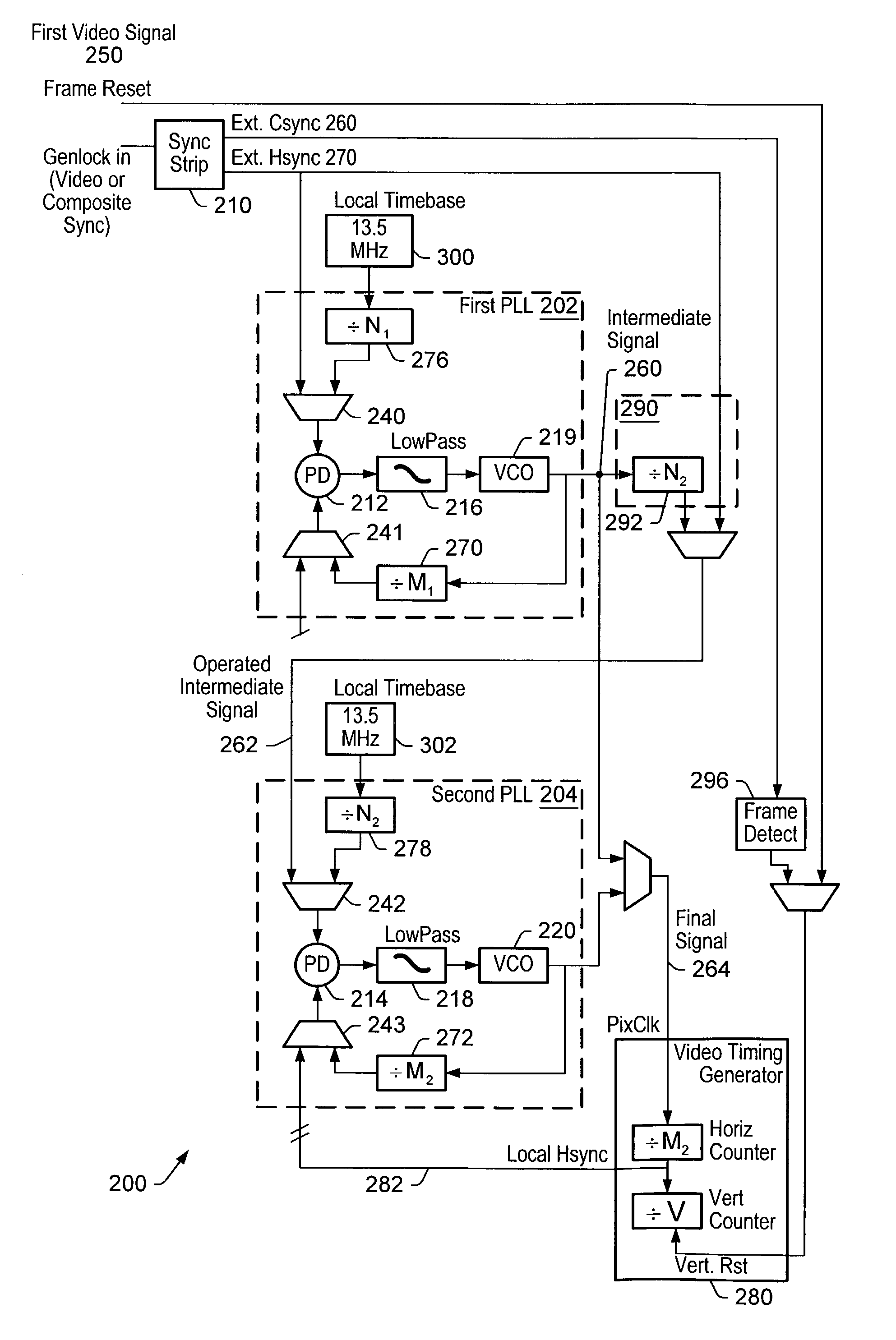
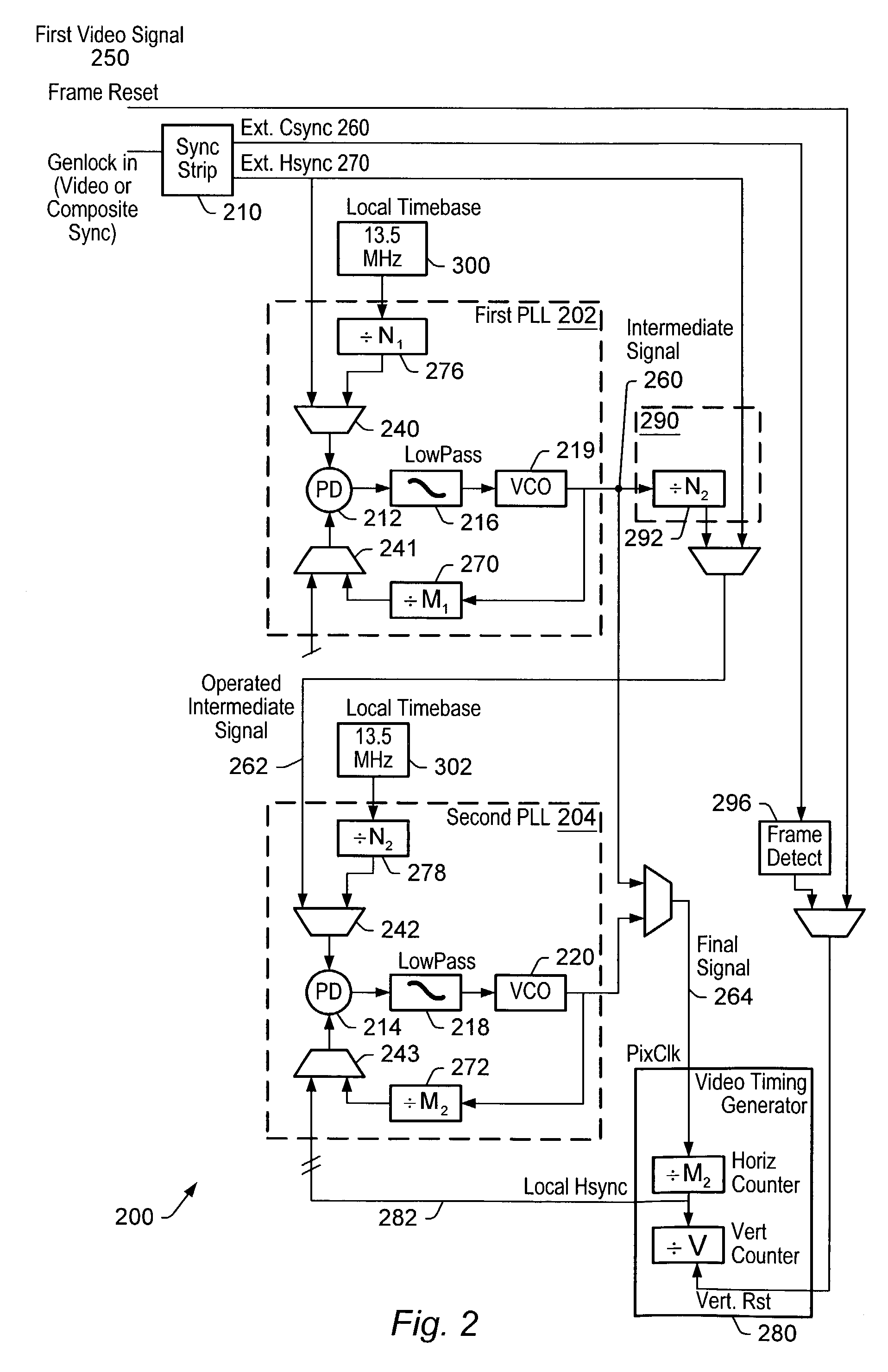
FIG. 2—Basic Block Diagram of a Video Synchronizing Device

[0025]FIG. 2 illustrates a basic block diagram of a video synchronizing ...


PUM


Abstract

In order to synchronize two dissimilar video formats, two or more phase locked loop circuits (PLL's) may be used in tandem. A first PLL circuit may be connected to the first video format (Master) and generate an intermediate frequency. A second PLL circuit may use the intermediate frequency as the timebase for generating the pixel clock for the second video format (Slave). One or more Slaves may be connected to the generated pixel clock. The video synchronizing device may be a part of a graphics system, such as a graphics accelerator.

Description

BACKGROUND OF THE INVENTIONDescription of the Related Art[0001]It is often desirable to synchronize several display devices such as monitors or projectors, such that their vertical retrace occurs simultaneously. This would be the case if the display devices were being filmed or videotaped, for example. Since display devices synchronize themselves to the video sources to which they are connected, achieving synchronization of the displays is equivalent to synchronizing their video sources. The video source can be a computer graphics accelerator.[0002]Traditionally synchronizing graphics accelerators is accomplished by means of asynchronous frame reset, where a Frame Reset signal from a first graphics accelerator, designated as a Master, is used to reset the video timing circuits of one or more second graphics accelerators, designated as Slaves. In this simple synchronization technique, known as Framelock, the video timing of the one or more Slaves is asynchronously reset at a set time...

Claims


Application Information

Patent Timeline
Patent Type & Authority Patents(United States)
IPC IPC(8): H04N5/262H03L7/06G09G5/12H04N5/073H04N5/12H04N5/46H04N5/74
CPCG09G5/12H04N5/073H04N5/126H04N21/4307H04N21/4305H04N5/74H04N5/46H04N21/43072
Inventor NAEGLE, NATHANIEL DAVID
Owner ORACLE INT CORP
Why Eureka
Try Eureka