Path search method of spread spectrum communication system and receiver using the method

a communication system and spread spectrum technology, applied in the field of path search method of spread spectrum communication system and receiver using the method, can solve the problems of reducing the tracking accuracy of reference reception timing at which the path search is carried out, enlarge the circuit scale, etc., and achieve the effect of reducing consumption power

Inactive Publication Date: 2006-07-04
RENESAS ELECTRONICS CORP
View PDF17 Cites 9 Cited by
  • Summary
  • Abstract
  • Description
  • Claims
  • Application Information

AI Technical Summary

Benefits of technology

[0013]Another object of the present invention is to provide a path search method of a spread spectrum communication system, which reduces consumpti...

Problems solved by technology

This results in the enlargement of the circuit scale of such as a memory that stores the delay profile data, a register, and the like.
The above-mentioned problem results from the conventional path search...

Method used


Image

  • Path search method of spread spectrum communication system and receiver using the method
  • Path search method of spread spectrum communication system and receiver using the method
  • Path search method of spread spectrum communication system and receiver using the method

Examples


first embodiment

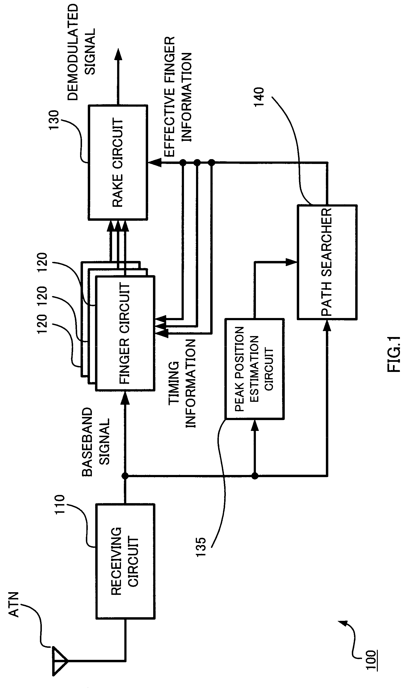
[0034]FIG. 1 illustrates a configuration of a substantial part 100 of the receiver of the spread spectrum communication system according to the first embodiment of the present invention.

[0035]The receiver substantial part 100 illustrated in FIG. 1 comprises a receiving Circuit 110, a plurality of finger circuits 120, a rake circuit 130, a peak position estimation circuit 135 and a path searcher 140.

[0036]The respective finger circuits 120 are supplied with baseband signals modulated by the receiving circuit 110 via an antenna ANT, and despread the supplied baseband signals at predetermined timing to be described later to output them to the rake circuit 130.

[0037]The rake circuit 130 performs RAKE combining of the despread signals output from the respective finger circuits 120 at aligned timing.

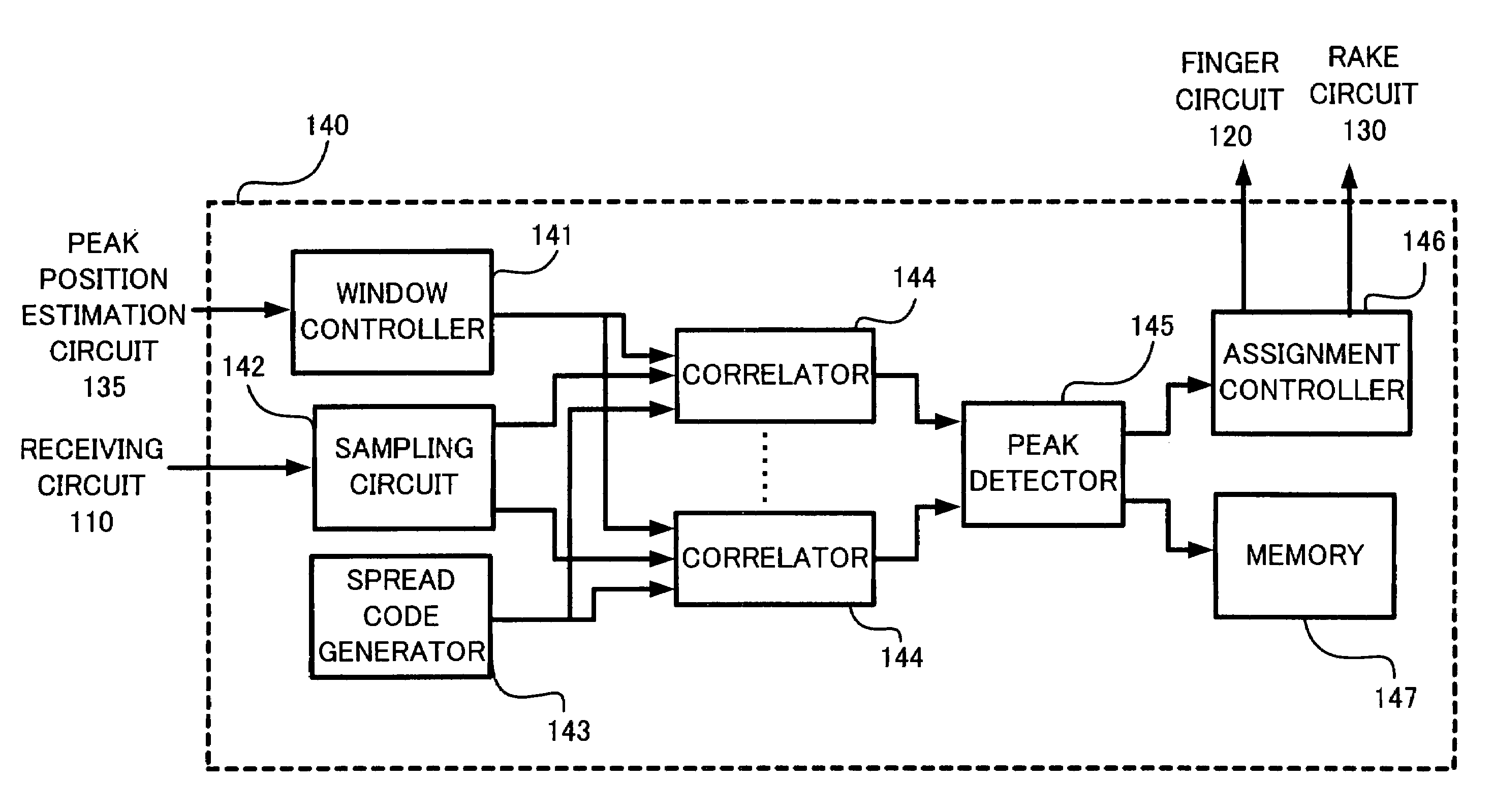
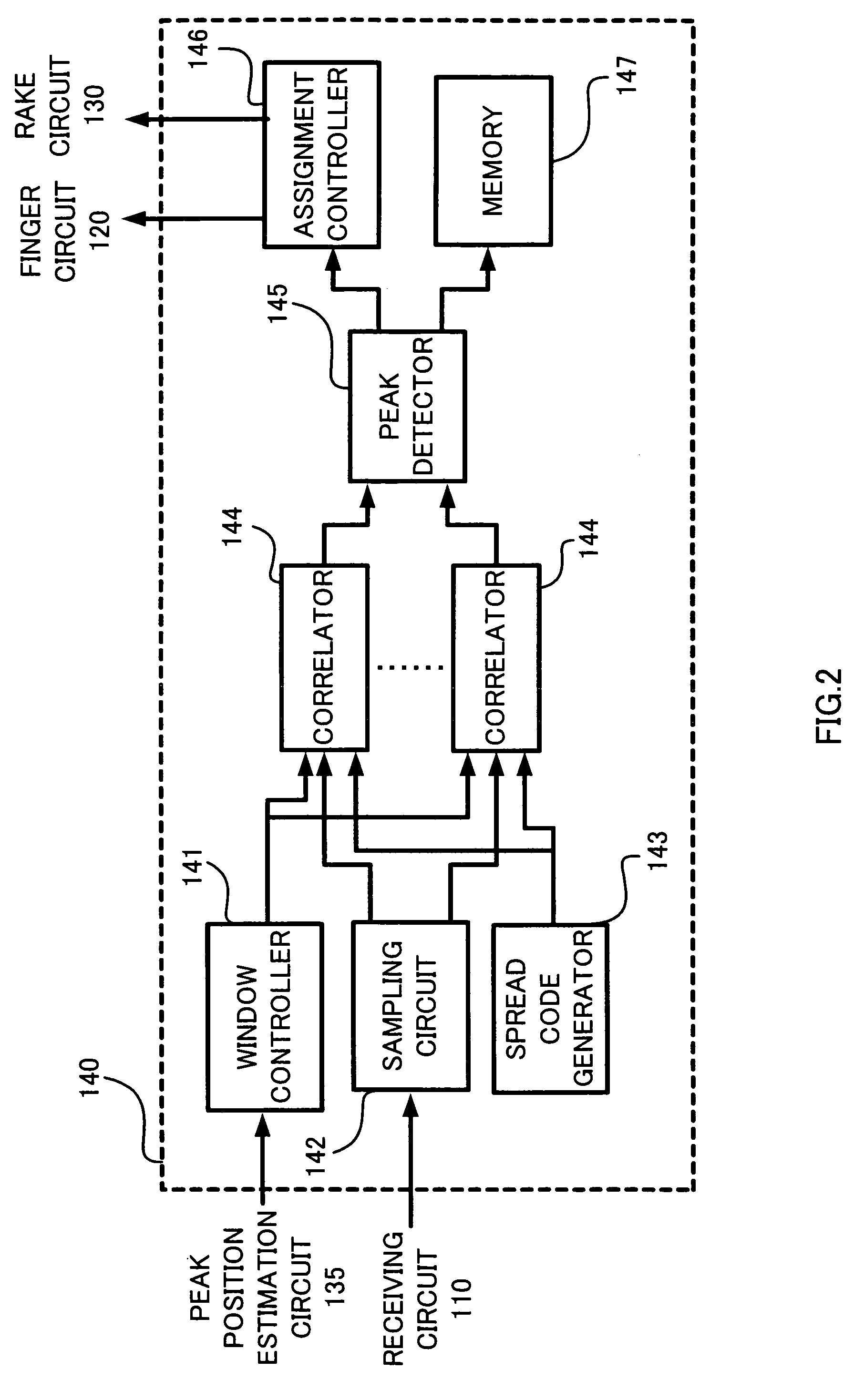
[0038]A peak position estimation circuit 135 estimates a peak position at a reference timing in the reception by the receiver, and supplies information representing the peak position to the pa...

second embodiment

[0054]FIG. 5 is a view to explain an operation of the receiver of the spread spectrum communication system of the second embodiment of the present invention. A receiver 200 of this embodiment has fundamentally the same configuration as that of the first embodiment except the point that the path search range is different from the first embodiment. As illustrated in FIG. 5, the search window is set on not only the right side of the tracking window but also the left side thereof, that is, a previous time region. Movement of the search window in this case is illustrated in FIG. 6A to FIG. 6D in order. it is noted that movement is returned to state illustrated in FIG. 6A after state illustrated in FIG. 6D.

[0055]In this receiver, since the path search range is wider than the case of the first embodiment illustrated in FIG. 3 and FIG. 4A, and FIG. 4B, there is a demerit in that much time is required to complete the path search. However, for example, even if the receiver is moved and refere...


PUM


Abstract

A receiver of a spread spectrum communication system comprises a plurality of despreading circuits, a rake circuit, and a path searcher. The plurality of despreading circuits despreads received signals having multipath components at predetermined timing allocated thereto. The rake circuit performs rake combining of the signals despread by despreading circuits. The path searcher forms a first window showing a part of a search range and calculates delay profile data of said received signals in said first window to search an effective path, forms at least one second window in the search range except said first window and calculates delay profile data of said received signals in said second window, and detects timing at which said received signals are despread based on calculated delay profile data to allocate the detected timing to said despreading circuits.

Description

BACKGROUND OF THE INVENTION[0001]1. Field of the Invention[0002]The present invention relates to a path search method of a spread spectrum communication system and a receiver using the method, and more particularly to a path search method of a spread spectrum communication system, which is effective in miniaturization and reduction in consumption power and a receiver using the method.[0003]2. Description of the Related Art[0004]The receiver of the spread spectrum communication system is used in a CDMA (Code Division Multiple Access) and the like.[0005]Generally, in the receiver of the spread spectrum communication system, a multipart occurs due to reflection and the like. For this reason, regarding the respective multipath components, the receiver of the spread spectrum communication system detects distribution (delay profile) of reception power with respect to delay time at its arrival time, and manages the delay profile data individually.[0006]The receiver of the spread spectrum c...

Claims


Application Information

Patent Timeline
IPC IPC(8): H04B1/69H04B1/713H04B1/707H04B1/7075H04B1/7113H04B7/02
CPCH04B1/70754H04B1/7113H04B1/712H04B1/7117
Inventor SAITO, TADASHIOHSUGE, MICHIHIROTAMURA, KOUITI
Owner RENESAS ELECTRONICS CORP
Why Eureka
Try Eureka