Method and apparatus for reducing DC offsets in a communication system

a communication system and dc offset technology, applied in the field of electromagnetic (em) signal frequency conversion, can solve the problems of inability to accurately receive or down-convert modulated carrier signals in communication systems, unsuitable dc offset voltages in receiver channels, and saturation of receiver channels, so as to achieve the effect of reducing dc offs

Inactive Publication Date: 2006-07-04
PARKER VISION INC
View PDF680 Cites 121 Cited by
  • Summary
  • Abstract
  • Description
  • Claims
  • Application Information

AI Technical Summary

Benefits of technology

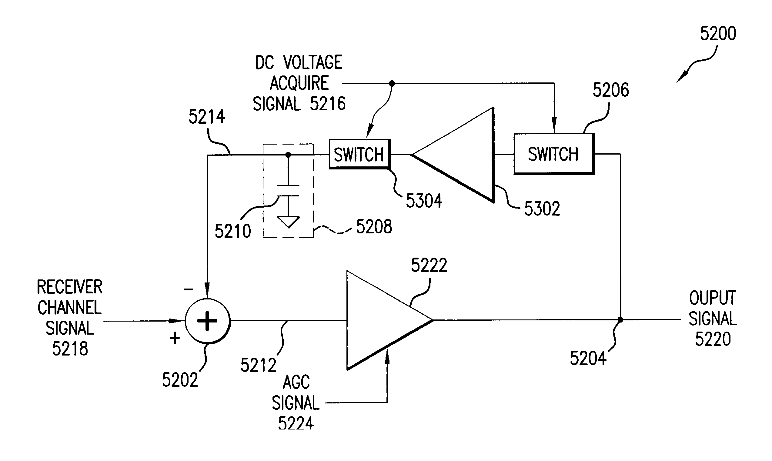
[0010]In an embodiment, a feedback loop circuit is used to reduce DC offsets in the WLAN receiver channel, according to the above stated method. A receiver channel signal is coupled as a first input

Problems solved by technology

Numerous problems exist in attempting to accurately receive or down-convert modulated carrier signals in communication systems.
One such problem is when unwanted DC offset voltages exist in receiver channels.
This unwanted DC offset can en

Method used


Image

  • Method and apparatus for reducing DC offsets in a communication system
  • Method and apparatus for reducing DC offsets in a communication system
  • Method and apparatus for reducing DC offsets in a communication system

Examples


Embodiment Construction

Table of Contents

[0084]1. Introduction[0085]2. Universal Frequency Translation[0086]2.1 Frequency Down-Conversion[0087]2.2 Optional Energy Transfer Signal Module[0088]2.3 Impedance Matching[0089]2.4 Frequency Up-Conversion[0090]2.5 Enhanced Signal Reception[0091]2.6 Unified Down-Conversion and Filtering[0092]3. Example Down-Converter Embodiments of the Invention[0093]3.1 Receiver Embodiments[0094]3.1.1 In-Phase / Quadrature-Phase (I / Q) Modulation Mode Receiver Embodiments[0095]4. DC Offset and Circuit Gain Considerations and Corrections[0096]4.1 Overview of DC Offset[0097]4.2 Exemplary Communications System Receiver Channel[0098]4.3 Embodiments for Cancellation of DC Offset by Closed Feedback Loop[0099]4.3.1 Variable Frequency Response Embodiments of the Present Invention[0100]4.3.2 Operation of the Closed Feedback Loop of the Present Invention[0101]4.4 Embodiments for Cancellation of DC Offset by Open Feedback Loop[0102]4.4.1 Nulling the Receiver Channel Input Signal[0103]4.4.1.1 Exa...


PUM


Abstract

Methods and apparatuses for reducing DC offsets in a communication system are described. In a first aspect, a feedback loop circuit reduces DC offset in a wireless local area network (WLAN) receiver channel. The frequency response of the feedback loop circuit can be variable. In a second aspect, a circuit provides gain control in a WLAN receiver channel. The stored DC offset is subtracted from the receiver channel. First and second automatic gain control (AGC) amplifiers are coupled in respective portions of the receiver channel. In a third aspect, a feedback loop circuit reduces DC offset in a WLAN receiver channel. The feedback loop circuit includes a storage element that samples and stores receiver channel DC offset. The loop is opened, and the DC offset stored in the storage element is subtracted from the receiver channel. Circuits for monitoring DC offset, and for providing control signals for controlling the frequency response of the DC offset reducing circuits are also provided.

Description

CROSS-REFERENCE TO RELATED APPLICATIONS[0001]This application is a continuation-in-part of application Ser. No. 09 / 986,764, filed Nov. 9, 2001, and claims the benefit of U.S. Provisional Application No. 60 / 384,840, filed Jun. 4, 2002, which are both herein incorporated by reference in their entirety.STATEMENT REGARDING FEDERALLY-SPONSORED RESEARCH AND DEVELOPMENT[0002]Not applicable.REFERENCE TO MICROFICHE APPENDIX / SEQUENCE LISTING / TABLE / COMPUTER PROGRAM LISTING APPENDIX (SUBMITTED ON A COMPACT DISC AND AN INCORPORATION-BY-REFERENCE OF THE MATERIAL ON THE COMPACT DISC)[0003]Not applicable.BACKGROUND OF THE INVENTION[0004]1. Field of the Invention[0005]The present invention relates to frequency conversion of electromagnetic (EM) signals. More particularly, the present invention relates to reducing or eliminating DC offset voltages when down-converting a signal in a communication system.[0006]2. Background Art[0007]Electromagnetic (EM) information signals (baseband signals) include, b...

Claims


Application Information

Patent Timeline
IPC IPC(8): H04B1/10H04B1/30
CPCH03G3/20H04B1/30
Inventor RAWLINS, GREGORY S.BROWN, KEVINRAWLINS, MICHAEL W.SORRELLS, DAVID F.
Owner PARKER VISION INC
Why Eureka
Try Eureka