Microphone with improved sound inlet port

a technology of inlet nozzle and microphone, which is applied in the direction of transducer types, mouthpiece/microphone attachments, frequency/directions obtained arrangements, etc., can solve the problem of large dimensions of the inlet nozzle, and achieve the effect of facilitating the installation of the microphon

Inactive Publication Date: 2006-07-04
SONION NEDERLAND
View PDF155 Cites 135 Cited by
  • Summary
  • Abstract
  • Description
  • Claims
  • Application Information

AI Technical Summary

Benefits of technology

[0006]The inventive sound inlet plate is mounted on the first exterior surface and defines (possibly in combination with the first exterior surface) a passageway for transmitting sound to the aperture leading to the inner volume. The passageway receives the sound from an opening in the sound inlet plate, the opening being offset from the location at which the aper

Problems solved by technology

The large dimensions of the inlet nozzle can be a problem because hearing aids often have very limited space.
Further, the front volume and back volume within the microphone housing are typically of different sizes, causing the inlet nozzle, which is placed near the front volume, to be located asymmetrically on one of the exterior sur

Method used


Image

  • Microphone with improved sound inlet port
  • Microphone with improved sound inlet port
  • Microphone with improved sound inlet port

Examples


Embodiment Construction

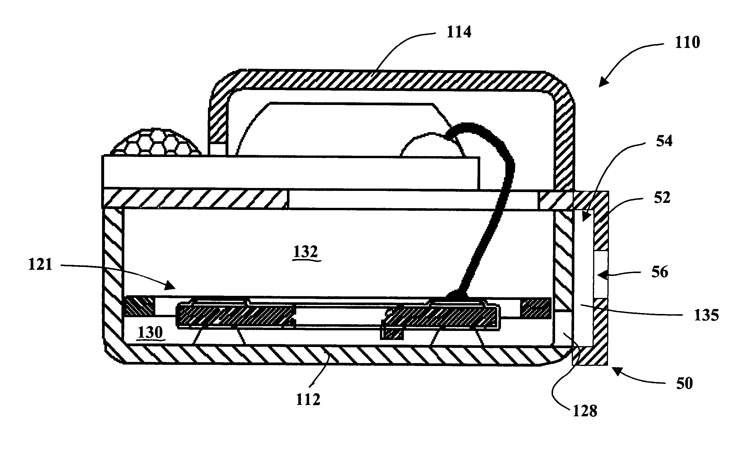
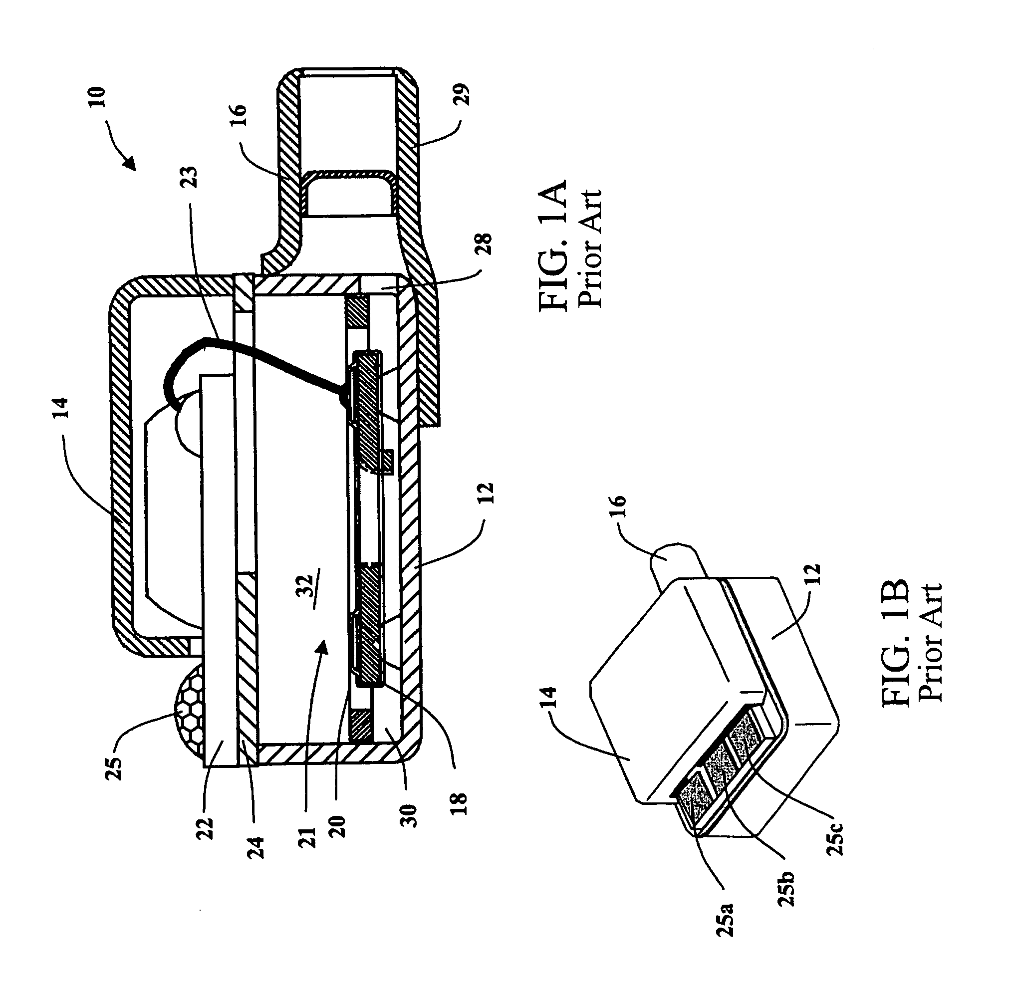
[0017]FIGS. 1A–1B illustrate a typical prior art microphone 10 The microphone 10 includes a case or housing 12, a cover 14, and a sound inlet nozzle 16 through which sound enters the housing 12. Within the housing 12, a backplate 18 having a charged electret layer works in conjunction with a moveable diaphragm 20 to convert (i.e., transduce) the sound into an electrical signal. The combination of the backplate 18 and the diaphragm 20 is generally referred to as an electret-type transducing assembly 21, although the present invention is useful with other types of transducing assemblies, as well

[0018]A printed circuit board 22 is mounted on a mounting plate 24 The signal from the transducing assembly 21 is sent to the printed circuit board 22 via a wire connection 23 The signal is processed on the printed circuit board 22 (e.g. amplified) to produce an output signal Because only a portion of the printed circuit board 22 is covered by the cover 14, one of the set of contacts 25a (FIG. ...


PUM


Abstract

A microphone comprises a housing defining an inner volume and including a first exterior surface with an aperture leading to the inner volume. The microphone includes a transducing assembly within the housing for converting sound into an electrical signal. A sound inlet plate defines, typically in combination with the first exterior surface, a passageway for transmitting sound to the aperture The passageway receives the sound from an opening in the sound inlet plate. The opening is offset from the location at which the aperture is positioned on the exterior surface. The sound inlet plate is made very thin so that it does not extend substantially away from the housing.

Description

FIELD OF THE INVENTION[0001]The present invention relates generally to electroacoustic transducers and, in particular, to a microphone or listening device with an improved sound inlet port.BACKGROUND OF THE INVENTION[0002]Miniature microphones, such as those used in hearing aids, convert acoustical sound waves into an audio signal, which is processed (e.g., amplified) and sent to a receiver of the hearing aid. The receiver then converts the processed signal to acoustical sound waves that are broadcast towards the eardrum. In one typical microphone, a moveable diaphragm and a charged backplate convert the sound waves into the audio signal. The diaphragm divides the inner volume of the microphone into a front volume and a rear volume Sound waves enter the front volume of the microphone via a sound inlet.[0003]Most prior art microphones, such as the prior art microphone of FIG. 1, have a sound inlet that includes a large inlet nozzle for receiving sound from the ambient environment. Th...

Claims


Application Information

Patent Timeline
IPC IPC(8): H04R9/08H04R25/00H04R1/08H04R1/28H04R1/38H04R19/01
CPCH04R1/08H04R25/604H04R19/016H04R1/38
Inventor VAN DOORN, JAN MARINUSGESKUS, MIKERAYMANN, THOMAS ANDREAS
Owner SONION NEDERLAND
Why Eureka
Try Eureka