Radio base station system and central control station with unified transmission format

a technology of radio base station and transmission format, applied in the direction of network traffic/resource management, sonic/ultrasonic/infrasonic transmission, electrical equipment, etc., can solve the problems of difficult equipment sharing and excessive facility investment, and achieve the effect of efficient use of hardware resources

Inactive Publication Date: 2006-07-04
NTT DOCOMO INC
View PDF20 Cites 175 Cited by
  • Summary
  • Abstract
  • Description
  • Claims
  • Application Information

AI Technical Summary

Benefits of technology

[0020]In this manner, the demultiplexing unit demultiplexes signals supplied from the upper-level station, and shared use of transceivers between radio communication and optical communication can be made by converting the demultiplexed signals into the signals having the unified transmission format. This achieves efficient use of hardware resources.
[0021]Further, the distribution unit distributes the signals having the unified transmission format, so that switching of communication links can be engaged by taking into account traffic conditions in accordance with indications of signal destinations. This makes it possible for different communication links to make shared use of the signal conversion units.

Problems solved by technology

When communication links between the central control station and the radio base stations varies in their types as shown in the case of FIG. 10, shared use of equipment is difficult because of different transmission formats.
This may result in an excessive investment in facility.

Method used


Image

  • Radio base station system and central control station with unified transmission format
  • Radio base station system and central control station with unified transmission format
  • Radio base station system and central control station with unified transmission format

Examples


first embodiment

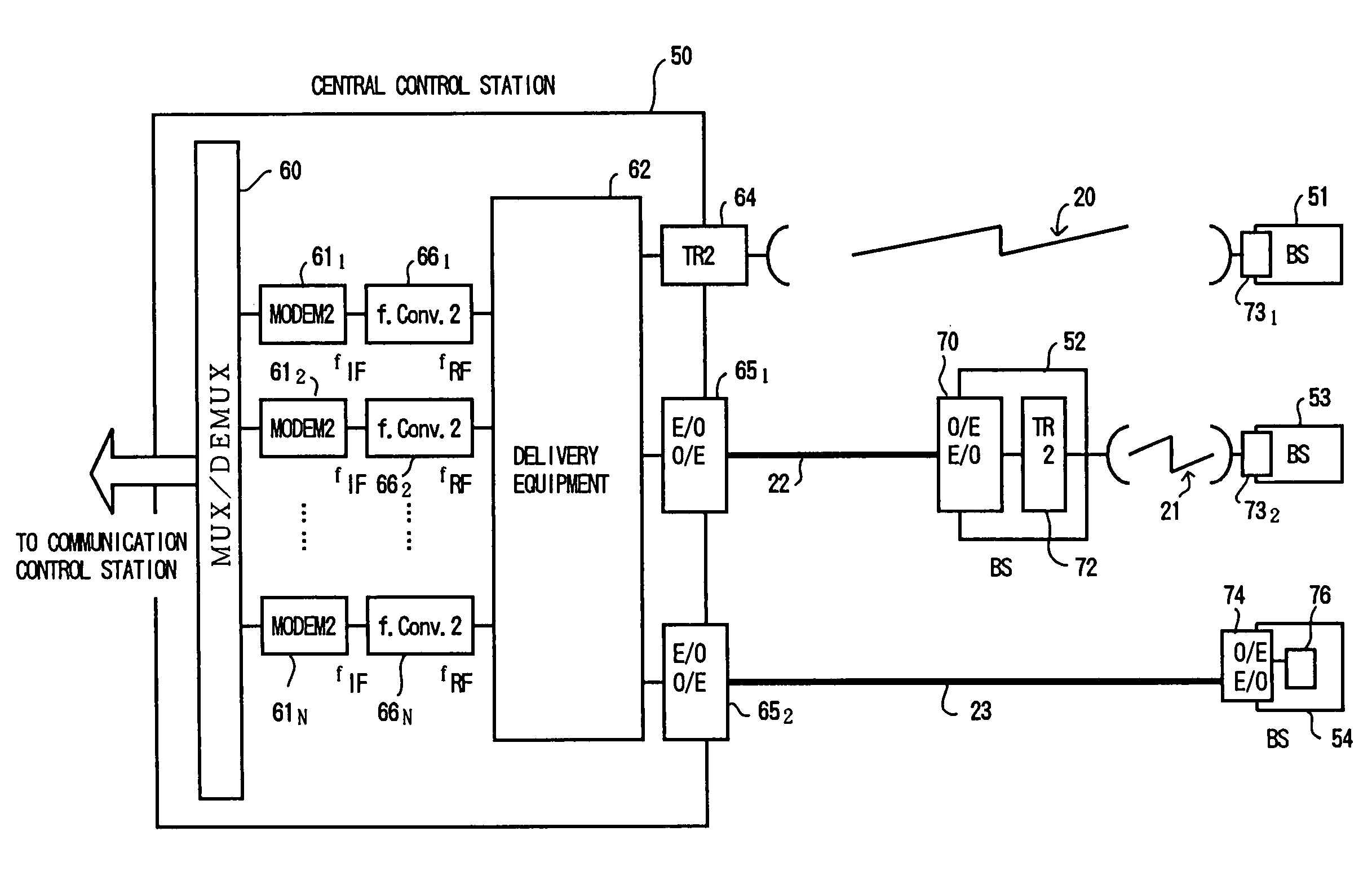
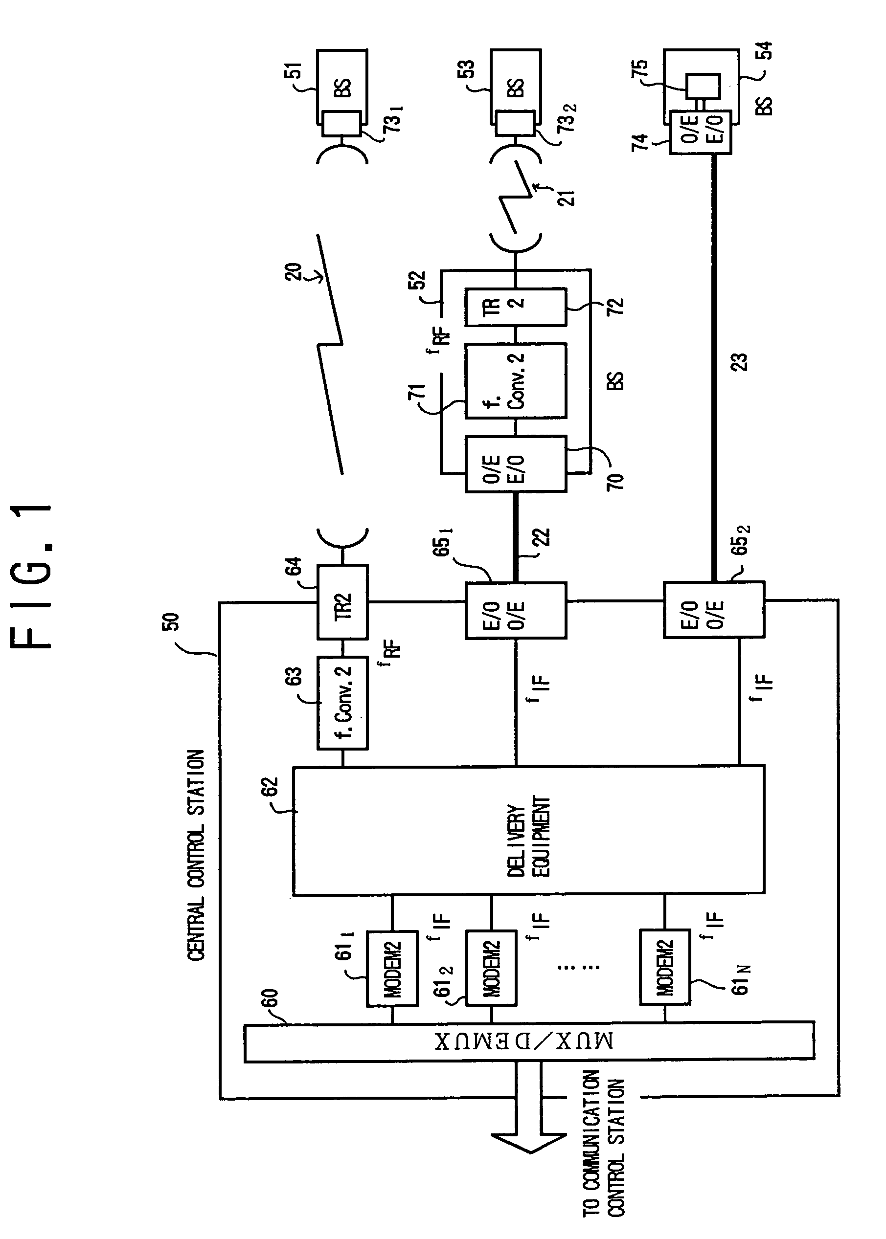
[0053]FIG. 1 is a block diagram showing the present invention.

[0054]A central control station 50 (which may be a cluster central control station when base stations having a cluster structure are used) includes centrally located modems (MODEM2) 611 through 61N for communication between the central control station 50 and radio base stations 51, 52, and 54. Signals arriving from the communication control station are demultiplexed by multiplex / demultiplex equipment 60 to be supplied to the modems 611 through 61N.

[0055]Upon receiving the signals, the modems 611 through 61N generate signals having intermediate frequency (IF). The IF signals output from the modems 611 through 61N are distributed by delivery equipment 62 to communication links. In respect of a radio communication link 20, a frequency converter (f.Conv.2) 63 converts the IF signals into signals (RF) having a radio frequency (RF), and a radio transceiver (TR2) 64 transmits the RF signals to the radio base station 51.

[0056]In ...


PUM


Abstract

A central control station, which controls radio base stations connected thereto via radio links and optical fiber links, includes a demultiplexing unit which demultiplexes signals supplied from an upper-level station, signal conversion units which convert the respective demultiplexed signals into converted signals having a unified transmission format, and a distribution unit which distributes the converted signals to the radio links and the optical fiber links.

Description

BACKGROUND OF THE INVENTION[0001]1. Field of the Invention[0002]The present invention generally relates to a radio base station system and a central control station as well as to a method of processing signals at the central control station[0003]2. Description of the Related Art[0004]FIG. 10 is a block diagram showing a configuration of communication links between mobile-communication base stations.[0005]A central control station 30 (which may be a cluster central control station when base stations having a cluster structure are used) uses a radio communication link 20 and optical communication links 22 and 23 to establish communication links with radio base stations (BS) 31, 32, and 34, respectively. In the case of radio communication, the central control station 30 uses a multiplex / demultiplex equipment (MUX / DEMUX) 44 to supply signals to radio terminals as these signals are supplied from the communication control station. Base-band signals supplied to the terminals are modulated ...

Claims


Application Information

Patent Timeline
Patent Type & Authority Patents(United States)
IPC IPC(8): H04B10/00H04W24/00H04W28/06H04W92/00H04W92/12
CPCH04B10/25753
Inventor ABURAKAWA, YUJISUDA, HIROHITOYAMAO, YASUSHI
Owner NTT DOCOMO INC
Why Eureka
Try Eureka