
Disk apparatus

Inactive Publication Date: 2006-07-04
ALPINE ELECTRONICS INC
View PDF1 Cites 5 Cited by
  • Summary
  • Abstract
  • Description
  • Claims
  • Application Information

AI Technical Summary

Benefits of technology

[0006]The present invention has been made to overcome the above problems. An object of the present invention is to provide a disk apparatus in which the transmission of power from a common motor can be switched between a disk transfer mechanism and a disk selection mechanism, the switching can be made with a simple structure, and the switch timing can be precisely determined.
[0008]In the disk apparatus, since the disk transfer mechanism and the selection mechanism are driven by a common motor, the number of motors can be reduced. Furthermore, since the transmission path of the power is switched by the moving force produced when the disk transfer mechanism moves between the transfer-force transmitting position and the transfer-force interrupting position, the structure of the switching mechanism can be simplified, and the switch timing for the power transmission path can be determined precisely.
[0013]By being locked while the power of the motor is transmitted to the disk transfer mechanism, the selection mechanism can be prevented from being inadvertently moved, for example, by vibration, during the transfer of the disk.
[0014]By operating the lock member by the moving force of the disk transfer mechanism, it is possible to precisely determine the timing of locking and unlocking of the selection mechanism.
[0015]Preferably, the disk apparatus further includes an urging member that stably holds the selection mechanism in the first switching state and the second switching state. The urging member is, for example, a torsion spring. By thus providing the urging member that stably holds the switching mechanism in the first switching state and the second switching state, the state of the switching mechanism can be prevented from being inadvertently switched, for example, by vibration.

Problems solved by technology

However, the use of separate motors increases the cost of the apparatus and interferes with size reduction of the apparatus.

Method used


Image

  • Disk apparatus
  • Disk apparatus
  • Disk apparatus

Examples


Embodiment Construction

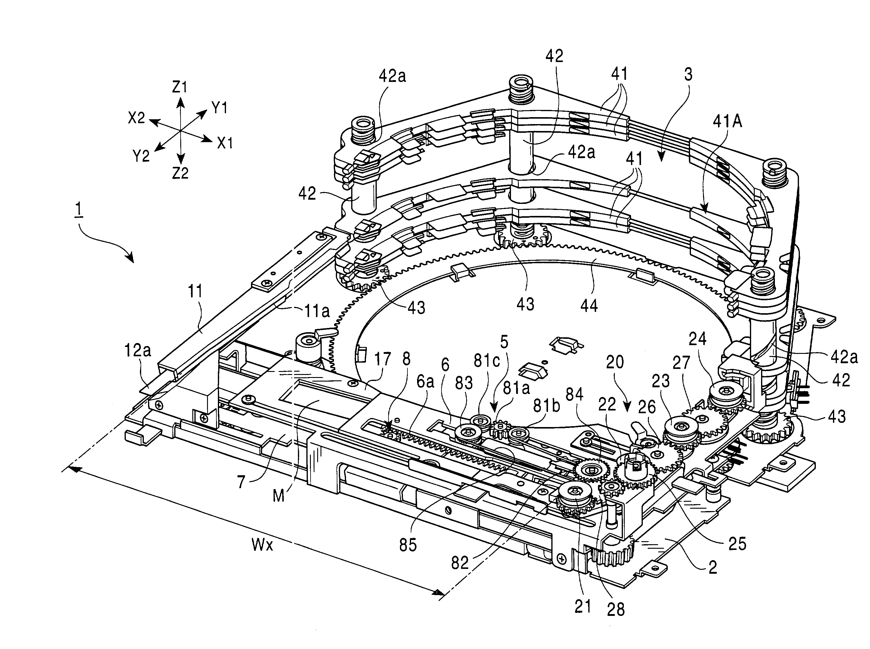
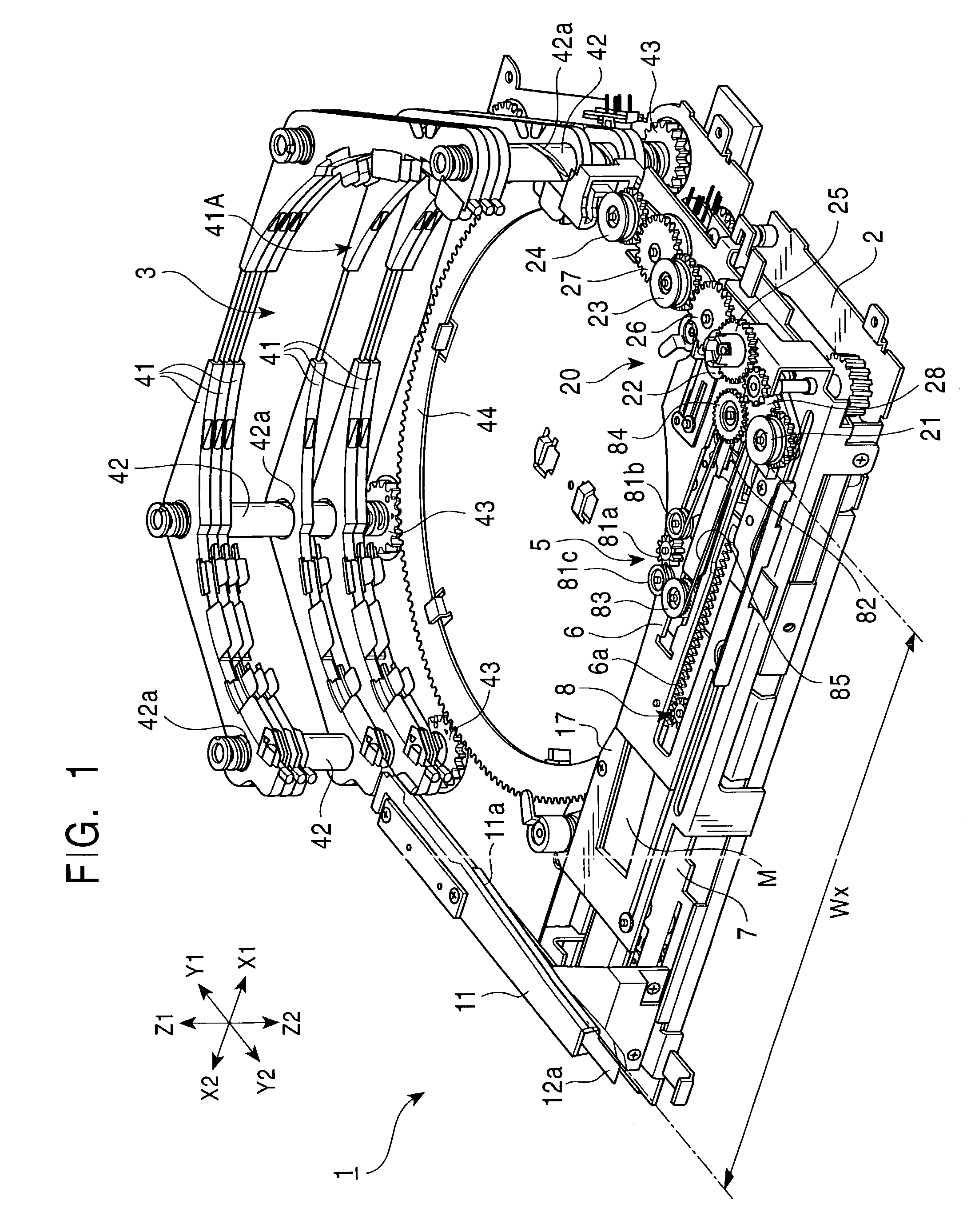
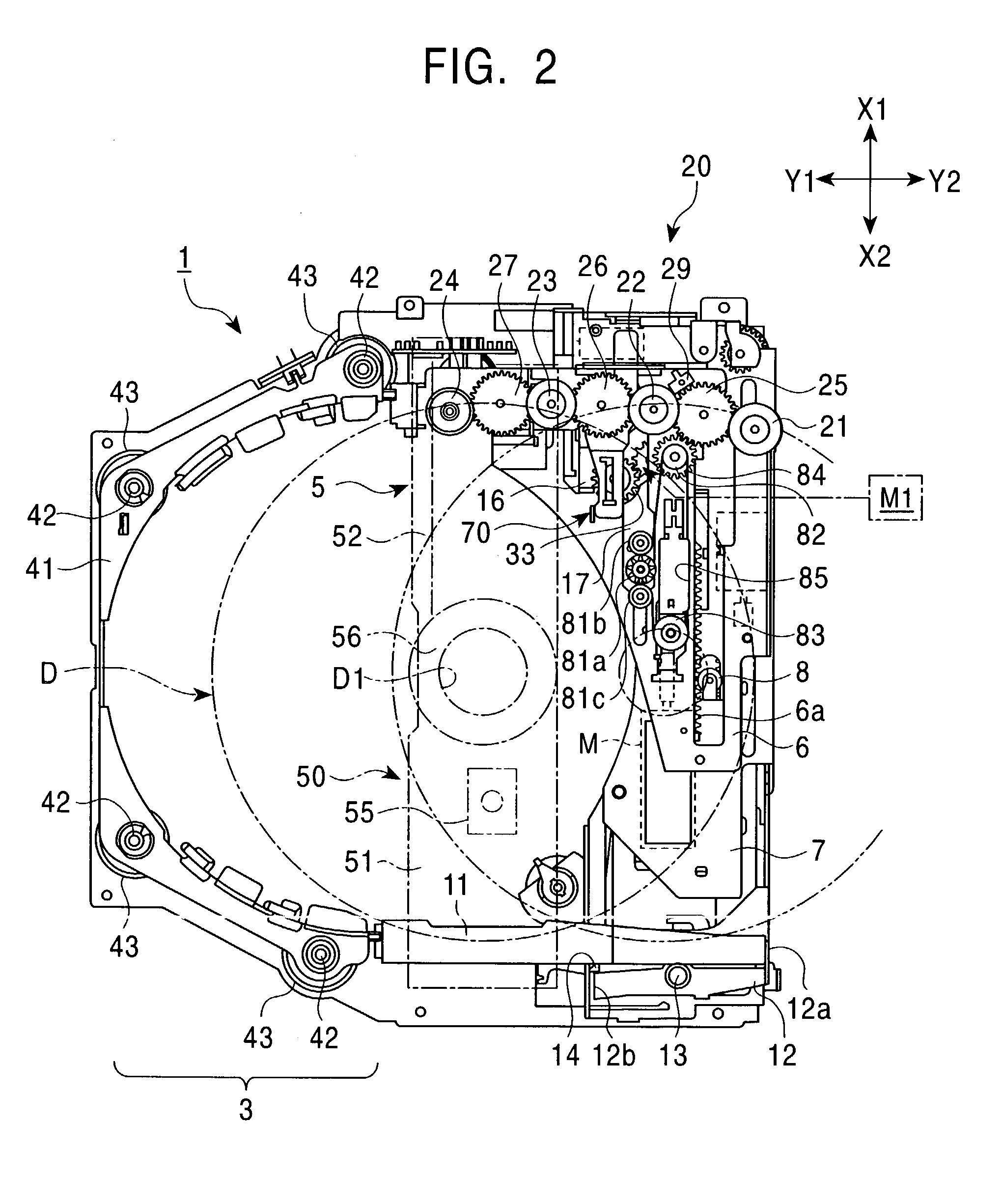
[0032]A disk apparatus 1 shown in FIGS. 1 and 2 is capable of playback and / or recording of small-diameter disks having a diameter of 8 cm and large-diameter disks having a diameter of 12 cm, such as CDs (compact disks) or DVDs (digital versatile disks). A plurality of disks of 12 cm in diameter can be stored inside the disk apparatus 1, and one of the disks is selected for driving.

[0033]As shown in FIG. 15, a face section 110 having a liquid crystal display panel 111 and various switches 112 is provided on the front side (Y2-side) of the main body of the disk apparatus 1. The face section 110 also has a loading slot 113 extending in the widthwise direction (X1-X2 direction). A stock section 3 in which a plurality of large-diameter disks can be stacked in the vertical direction (Z-direction) is disposed at the back side (Y1-side) of the disk apparatus 1. The large-diameter disks are held in disk holders 41 of the stock section 3, respectively, and are stored while being stacked in th...


PUM


Abstract

A disk apparatus includes a stock section for storing a plurality of stacked disks, a disk transfer mechanism for withdrawing a selected disk out of the stock section, a selection mechanism for causing the selected disk and the disk transfer mechanism to face each other, a rotating section for driving the disk, a common motor, a power transmission mechanism for selectively transmitting the power of the motor to the selection mechanism and to the disk transfer mechanism, and a switching mechanism for switching between a first switching state in which the power of the motor is transmitted to the disk transfer mechanism and a second switching state in which the power of the motor is transmitted to the selection mechanism. The switching mechanism is switched between the states by the moving force of the disk transfer mechanism moving between a transfer-force transmitting position and a transfer-force interrupting position.

Description

BACKGROUND OF THE INVENTION[0001]1. Field of the Invention[0002]The present invention relates to a disk-selection apparatus in which a disk selected from a plurality of disks stored in a stock section is withdrawn and driven, and more particularly, to a disk apparatus in which a selection mechanism for selecting a disk from a stock section and a disk transfer mechanism for transferring a disk are driven by a common motor.[0003]2. Description of the Related Art[0004]In some disk apparatuses to be mounted, for example, in cars, a plurality of disks is held in a stock section, and a selected disk is withdrawn from the stock section for playback and recording. These disk apparatuses include a disk transfer mechanism for transferring a disk to the stock section and withdrawing a disk from the stock section, and a selection mechanism for changing the relative positions of the stock section and the disk transfer mechanism so that the disk selected from the stock section and the disk transf...

Claims


Application Information

Patent Timeline
IPC IPC(8): G11B33/02G11B17/22
CPCG11B17/223G11B17/021
Inventor OTSUKI, AKIRA
Owner ALPINE ELECTRONICS INC
Learn More