
Air conditioner

a technology for air conditioners and air conditioners, which is applied in the direction of cooling fluid circulation, lighting and heating apparatus, and domestic cooling apparatus, etc. it can solve the problems of reducing the heating value of the operation of the driving auxiliary heating device is not performed, and the energy consumed in the auxiliary heating device is reduced, so as to enhance the energy-saving capability of the air conditioner and reduce the energy consumption. the effect of auxiliary heating device consumption and enhancing the energy-saving capacity

Inactive Publication Date: 2006-07-11
YAZAKI ENERGY SYST
View PDF24 Cites 11 Cited by
  • Summary
  • Abstract
  • Description
  • Claims
  • Application Information

AI Technical Summary

Benefits of technology

Enhances energy-saving capabilities by reducing energy consumption in the auxiliary heating device, ensuring efficient cooling and heating operations without unnecessary heating or cooling.

Problems solved by technology

Thus, when the amount of exhaust heat is sufficient for cooling the refrigerant in the absorption chiller regardless of the temperature of the heat transfer medium, that is, when the temperature of the refrigerant cooled by the absorption chiller is at a level at which the cooling load can be sufficiently cooled, the operation of driving the auxiliary heating device is not performed.
Thus, when the temperature of the refrigerant is at a level, which is sufficient for performing cooling, regardless of the temperature of the heat transfer medium, the operation of driving the auxiliary heating device is not performed.
This results in occurrences of operations, in which the auxiliary heating device stops immediately after driven, and in which the heating value of the auxiliary heating device is decreased just after increased.

Method used


Image

  • Air conditioner
  • Air conditioner
  • Air conditioner

Examples


first embodiment

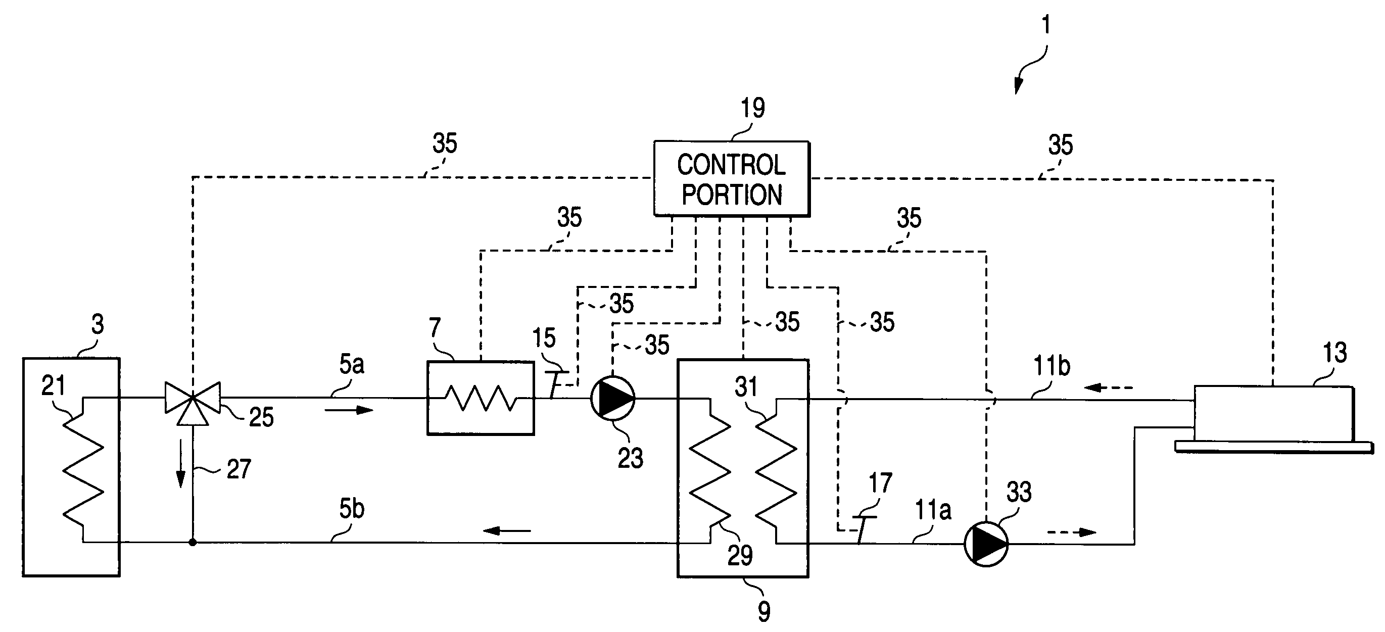
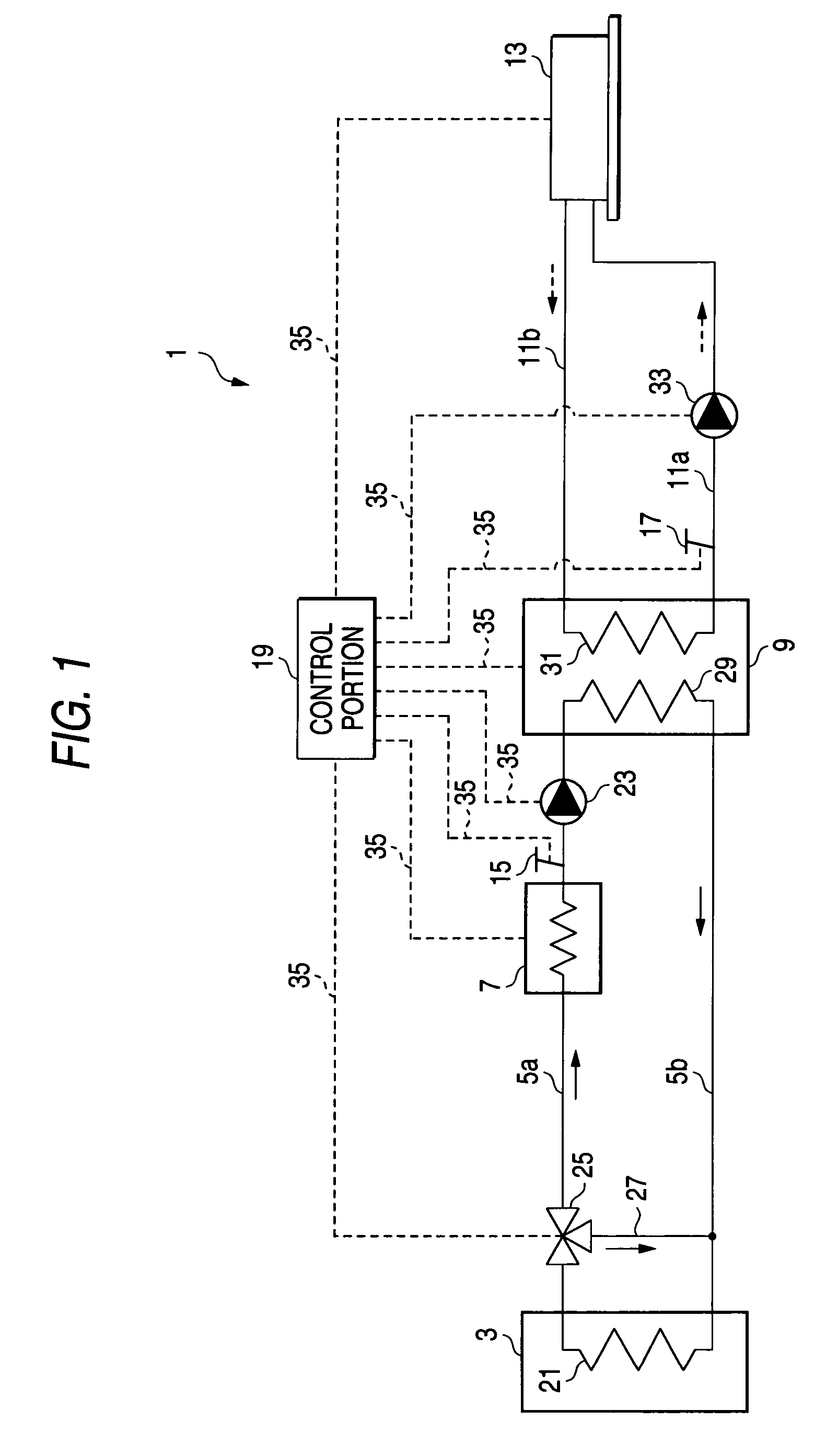
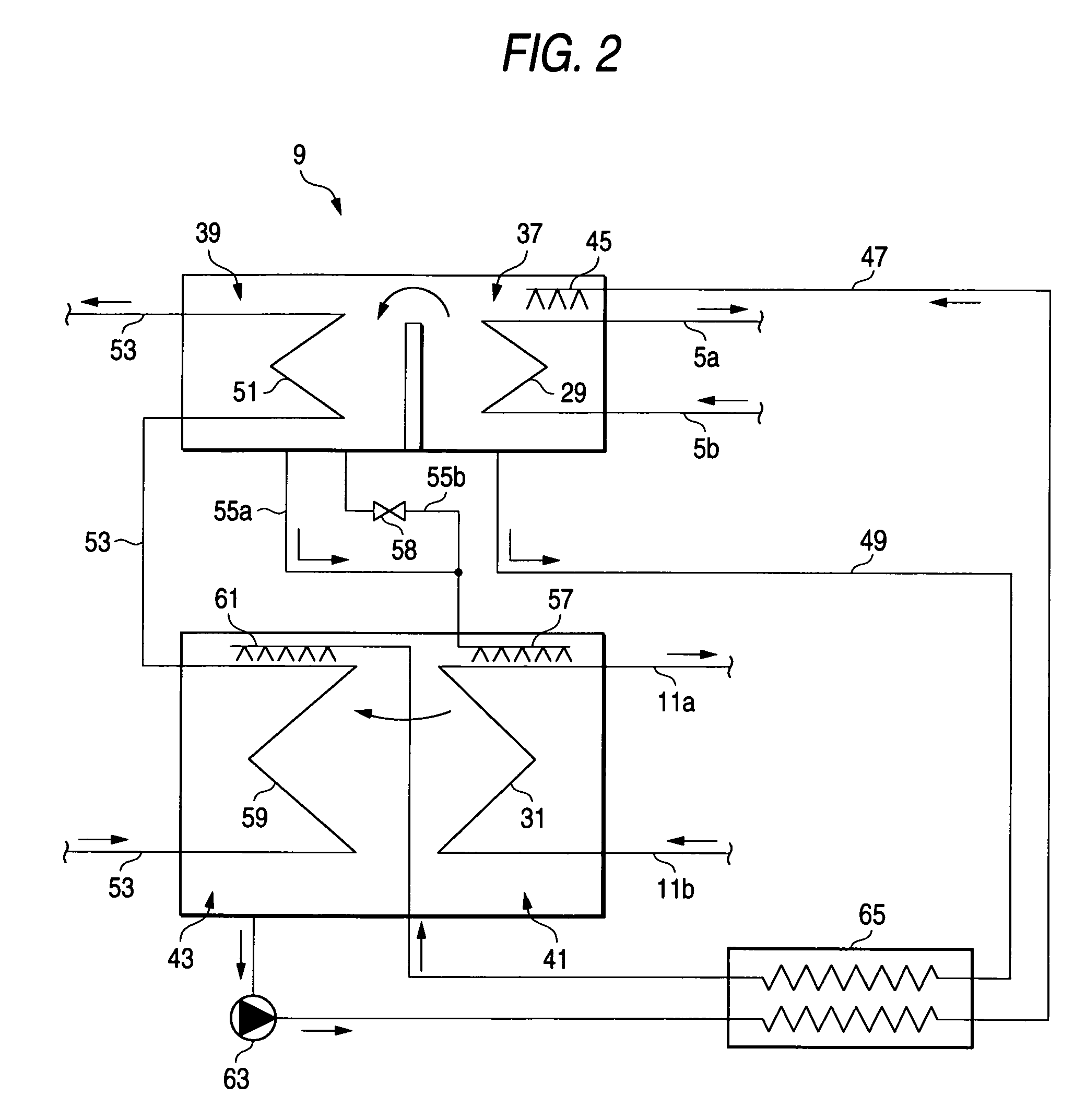
[0024]Hereinafter, a first embodiment of an air conditioner, to which the invention is applied, is described with reference to FIGS. 1 to 3B. FIG. 1 is a schematic diagram illustrating the configuration and operation of the first embodiment of the air conditioner to which the invention is applied. FIG. 2 is a schematic diagram illustrating the configuration and operation of an absorption chiller of the air conditioner that is the first embodiment to which the invention is applied.

[0025]FIG. 3A is a diagram illustrating an operation of an auxiliary heating device in the case that there is no exhaust heat from an exhaust heat source during a cooling operation. FIG. 3B is a diagram illustrating an operation of the auxiliary heating device in the case that there is exhaust heat from the exhaust heat source during a cooling operation. Incidentally, in the following description of this embodiment, the air conditioner designed specifically for cooling is described by way of example.

[0026]T...

second embodiment

[0044]A second embodiment of the air conditioner, to which the invention is applied, is described hereinbelow with reference to FIG. 4 to FIG. 5B. FIG. 4 is a schematic diagram illustrating the configuration and operation of the second embodiment of the air conditioner to which the invention is applied. FIG. 5A is a diagram illustrating an operation of an auxiliary heating device in the case that there is no exhaust heat from an exhaust heat source during a heating operation. FIG. 5B is a diagram illustrating an operation of the auxiliary heating device in the case that there is exhaust heat from the exhaust heat source during a heating operation. Incidentally, constituent elements of this embodiment, which are the same as those of the first embodiment, are designated by the same reference characters used for denoting the same constituent elements of the first embodiment. Further, the description of such constituent element is omitted herein. Hereunder, constituent elements and feat...

third embodiment

[0055]A third embodiment of the air conditioner, to which the invention is applied, is described hereinbelow with reference to FIG. 6. FIG. 6 is a schematic diagram illustrating the configuration and operation of the third embodiment of the air conditioner to which the invention is applied. Incidentally, constituent elements of this embodiment, which are the same as those of the first and second embodiments, are designated by the same reference characters used for denoting the same constituent elements of the first and second embodiments. Further, the description of such constituent element is omitted herein. Hereunder, constituent elements and features of the third embodiment, which differ from those of the first and second embodiments, are described.

[0056]The third embodiment differs from the first and second embodiments in that the air conditioner 1 of the first embodiment is designed specifically for cooling, and the air conditioner 67 of the second embodiment is designed specif...


PUM


Abstract

An air conditioner is provided that includes an exhaust heat recovery unit for recovering exhaust heat in a heat transfer medium, a heat transfer medium passage in which the heat transfer medium outputted from the exhaust heat recovery unit flows, an auxiliary heating device, heats the heat transfer medium, an absorption chiller driven by heat of the heat transfer medium, a refrigerant passage, through which a refrigerant outputted from the absorption chiller flows, an indoor unit to which the refrigerant is supplied through the refrigerant passage, a heat transfer medium temperature detector for detecting the temperature of the heat transfer medium flowing through the heat transfer medium passage, a refrigerant temperature detector for detecting the temperature of the refrigerant flowing through the refrigerant passage, and a control portion for controlling an operation of driving the auxiliary heating device.

Description

TECHNICAL FIELD[0001]The present invention generally relates to an air conditioner and, more particularly, to an air conditioner utilizing exhaust heat.BACKGROUND ART[0002]There have been devised air conditioners adapted to perform cooling, heating, or air-conditioning by utilizing exhaust heat from various heat-producing apparatuses, equipment, and facilities. Among such air conditioners which inventors of the invention devised, an air conditioner for performing at least cooling is devised in such a way as to include an absorption chiller of what is called the heat transfer medium drive type, which is adapted to recover exhaust heat and driven by a heat transfer medium, and as to perform cooling by supplying an indoor unit with a refrigerant cooled by the absorption chiller. Further, an air conditioner for performing at least heating is devised in such a way as to recover exhaust heat and as to perform heating by supplying an indoor unit with a heat transfer medium. Moreover, such ...

Claims


Application Information

Patent Timeline
Patent Type & Authority Patents(United States)
IPC IPC(8): F25D17/02F25B15/00F25B15/06F25B27/02F25B49/04
CPCF25B15/06F25B27/02F25B49/043Y02B30/625F25B2315/001Y02P80/15Y02A30/274F25B29/00
Inventor TONGU, SHINJIMATSUKIYO, TOMIYUKIARITA, KAZUHEIICHINO, YOSHIHIROOGAI, MASATOYAMAUCHI, AKIRAYAMAZAKI, TAKAYUKI
Owner YAZAKI ENERGY SYST
Learn More