Pressure regulating valve, in particular proportional pressure regulating valve

a technology of proportional pressure and valve valve, which is applied in the direction of fluid pressure control, process and machine control, instruments, etc., can solve the problem that the flow force occurring during the operation of the control edge of the valve piston is transmitted undiminished to the actuating system, and achieves the effect of improving the operation behavior

Inactive Publication Date: 2006-07-11
HYDAC FLUITECHNIK GMBH
View PDF9 Cites 14 Cited by
  • Summary
  • Abstract
  • Description
  • Claims
  • Application Information

AI Technical Summary

Benefits of technology

[0004]An object of the present invention is to provide a proportion

Problems solved by technology

Although high piston forces are not applied to the actuating system in a valve of this design, the flow forces occurring during operation on the control edges of the valve piston are transmitted undiminished to the actuati

Method used


Image

  • Pressure regulating valve, in particular proportional pressure regulating valve
  • Pressure regulating valve, in particular proportional pressure regulating valve

Examples


Embodiment Construction

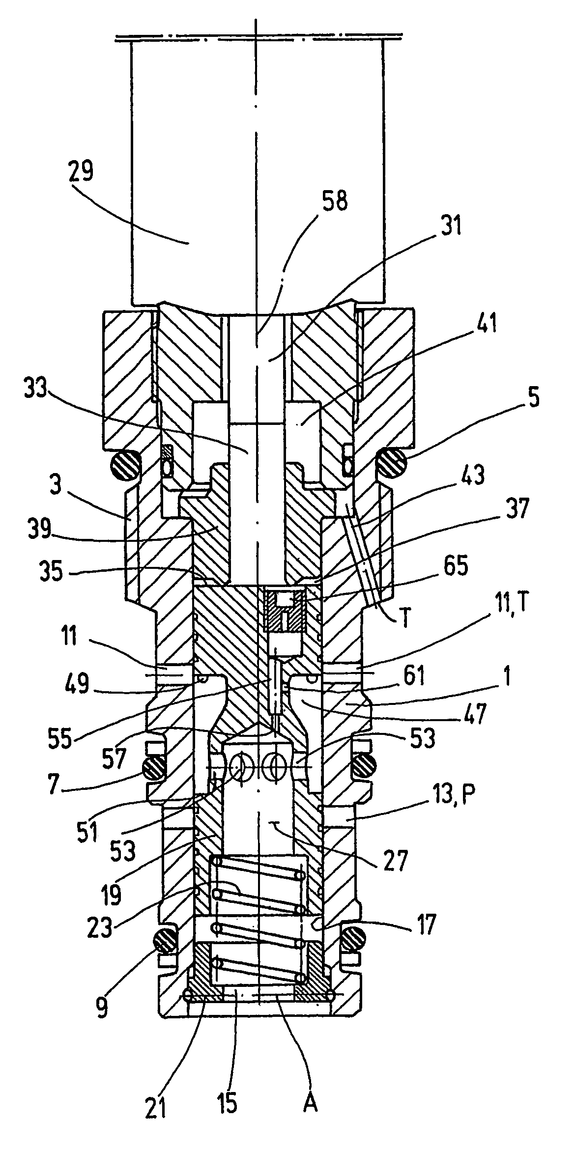
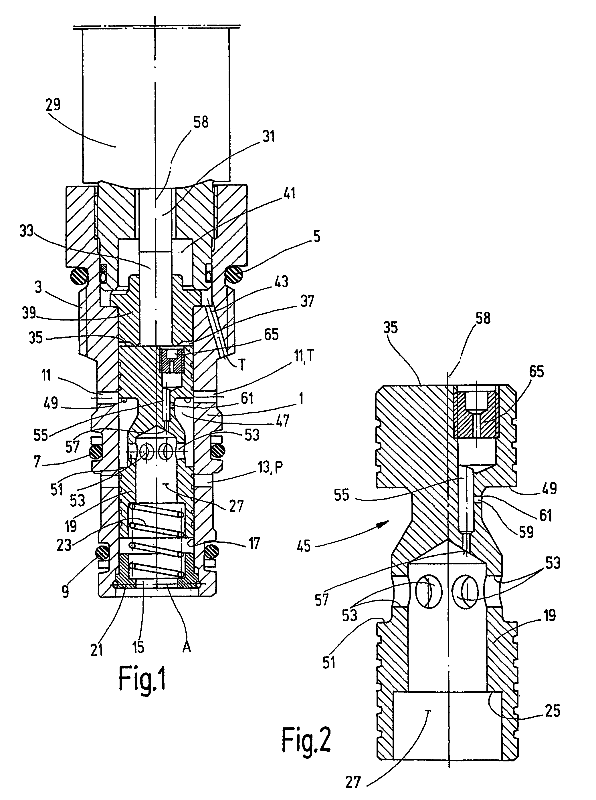
[0012]The pressure regulating valve shown in the drawings and described hereinafter is represented by a so-called screw-in valve. The sleeve-like valve housing 1 of the valve has external threading 3 so that it may be screwed into a valve recess (not shown). Annular sealing elements 5, 7 and 9 are seated on the valve housing 1 on the outer circumference side and are provided for sealing to prevent entry of fluid into the valve recess. In the circumferential area of the valve housing 1 situated between sealing elements 5 and 7, which area is sealed by the sealing elements 5 and 7 to prevent entry of fluid into the remaining circumferential area of the valve housing 1, the sleeve-like valve housing 1 has wall openings 11 which communicate with tank connection T of the associated fluid system when the valve housing 1 has been screwed into the valve recess. In the circumferential area situated between the sealing elements 7 and 9, the valve housing has wall openings 13 which are connect...


PUM


Abstract

A pressure regulating valve, in particular a proportional pressure regulating valve, includes a valve body (1) with at least a pump connection (P), a use connection (A) and a tank connection (T). A piston (19), capable of being displaced by a controllable actuating device (29), is guided in the valve body (1). At the periphery of the piston, a recess (45) is formed and defines a peripheral annular gap (47) delimited by the control edges (49, 51) of the piston (19). In the piston (19), a passage (55) provides fluid communication between the front surface of the piston (19), subjected to the use connection (A) pressure, and the rear surface (35) of the piston (19), adjacent to a pressure chamber (37) located behind. The passage (55) of the piston (19) has, in the region proximate to the piston front surface, a restriction zone (57). In a region away from the restriction zone (57) towards the rear of the piston surface (35), an orifice (59) faces the peripheral annular gap (47), and has a second restriction zone (61).

Description

FIELD OF THE INVENTION[0001]The present invention relates to a pressure regulating valve, in particular a proportional pressure regulating valve, having a valve housing with at least one pump connection, one application connection, and one tank connection. A valve piston is displaceable in the valve housing by a controllable actuating device. A recess in the valve piston circumference defines a circumferential annular space delimited by control edges of the piston. A passage formed in the piston establishes a fluid connection between the front side of the piston to which the pressure of the appliance connection is applied and the rear side of the piston adjacent to a pressure chamber on the rear side of the piston.BACKGROUND OF THE INVENTION[0002]Valves of this type are usually available through commercial channels. Since the predominant control pressure applied to the appliance connection acts on both sides of the valve piston in such directly controlled pressure limiting valves by...

Claims


Application Information

Patent Timeline
IPC IPC(8): F16K11/07F16K31/06G05D16/16G05D16/20
CPCG05D16/2013G05D16/2024Y10T137/86622Y10T137/86702
Inventor BRUCK, PETERHILLESHEIM, THORSTEN
Owner HYDAC FLUITECHNIK GMBH
Why Eureka
Try Eureka