Supercharge Your Innovation With Domain-Expert AI Agents!

Engine exhaust muffler with guide vanes imparting a successively alternating spiral swirl gas flow

a technology of spiral swirl and exhaust muffler, which is applied in the direction of engine components, machines/engines, silting apparatus, etc., can solve the problems of not being able to completely satisfy the damping system, and achieve the effect of good muffling and simple and compact construction

Inactive Publication Date: 2006-07-11
3W MODELLMOTOREN
View PDF17 Cites 23 Cited by
  • Summary
  • Abstract
  • Description
  • Claims
  • Application Information

AI Technical Summary

Benefits of technology

[0005]Accordingly, the invention is based on the object of providing a muffler which is of particularly simple construction and, firstly, consists of simply designed elements and, secondly, is particularly effective and flexible, with the result that it can also easily be adapted to different operating conditions.
[0008]According to the invention, deviations and deflections and also swirling of the gas flow therefore take place in the present case in such a manner that good muffling is produced.
[0009]At the same time, the muffler is of simple and compact construction especially when disk-shaped bodies in the form of circular rings in an axial arrangement one behind another are used.
[0010]Furthermore, the muffling effect can be adapted without any problem to the particular requirements, for which purpose the number of slotted deflecting elements and / or the number of guiding elements in the form of guide vanes per deflecting element and / or the shape and design of the guiding elements and / or the setting angles of the guiding elements and / or the orientation of the setting angle between adjacent deflecting elements can be changed. This permits specific adaptation to each application or to different engines in a simple manner.

Problems solved by technology

It is not possible for these damping systems to be completely satisfactory in respect of the damping action and / or the complexity and / or the adaptability to the particular application.

Method used


Image

  • Engine exhaust muffler with guide vanes imparting a successively alternating spiral swirl gas flow
  • Engine exhaust muffler with guide vanes imparting a successively alternating spiral swirl gas flow
  • Engine exhaust muffler with guide vanes imparting a successively alternating spiral swirl gas flow

Examples


Embodiment Construction

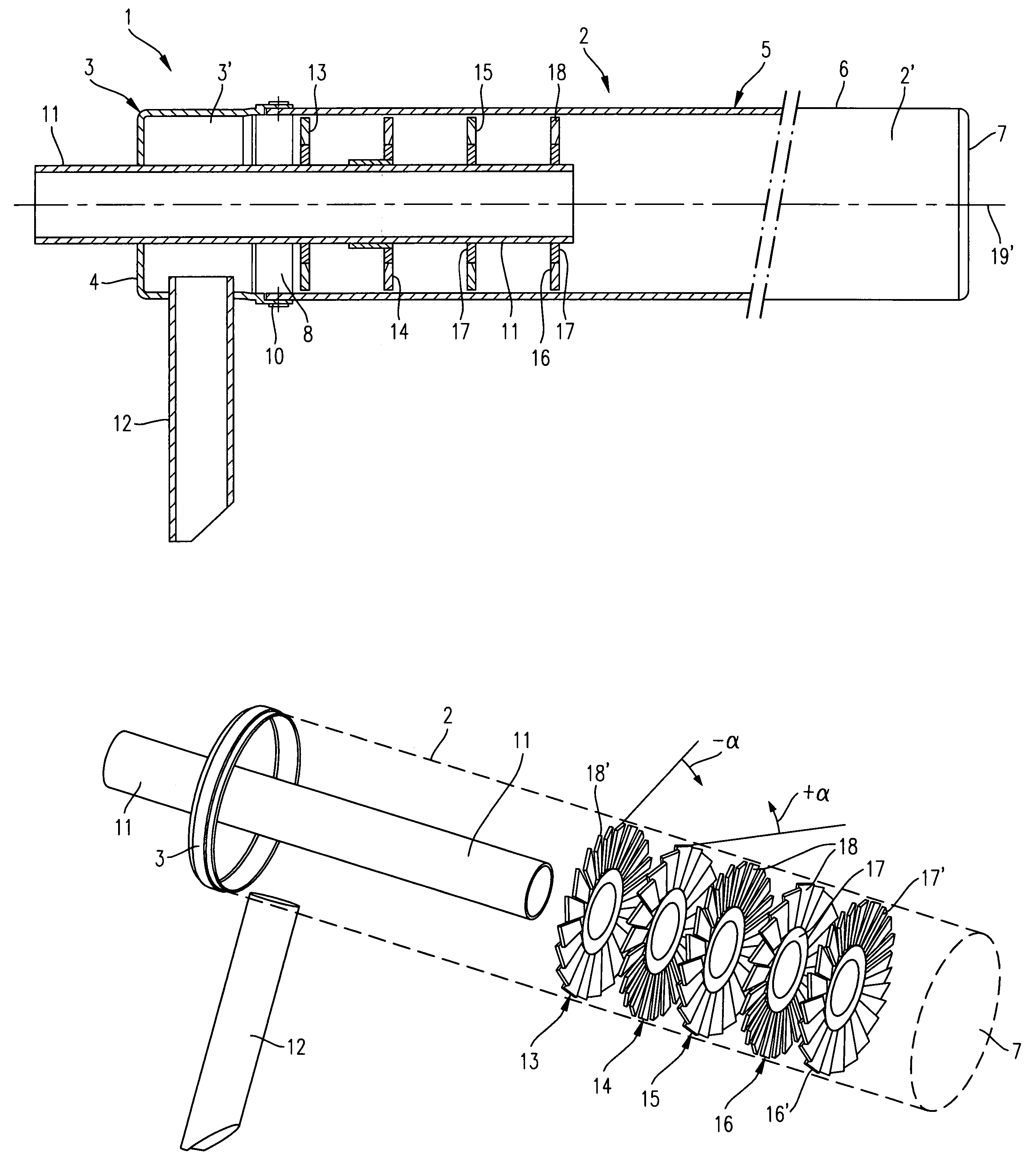
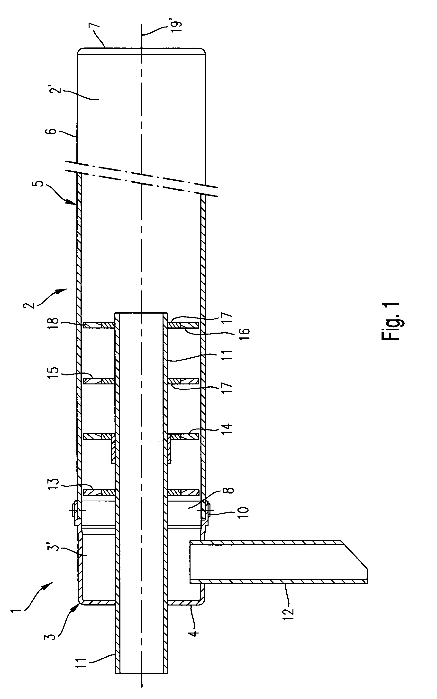
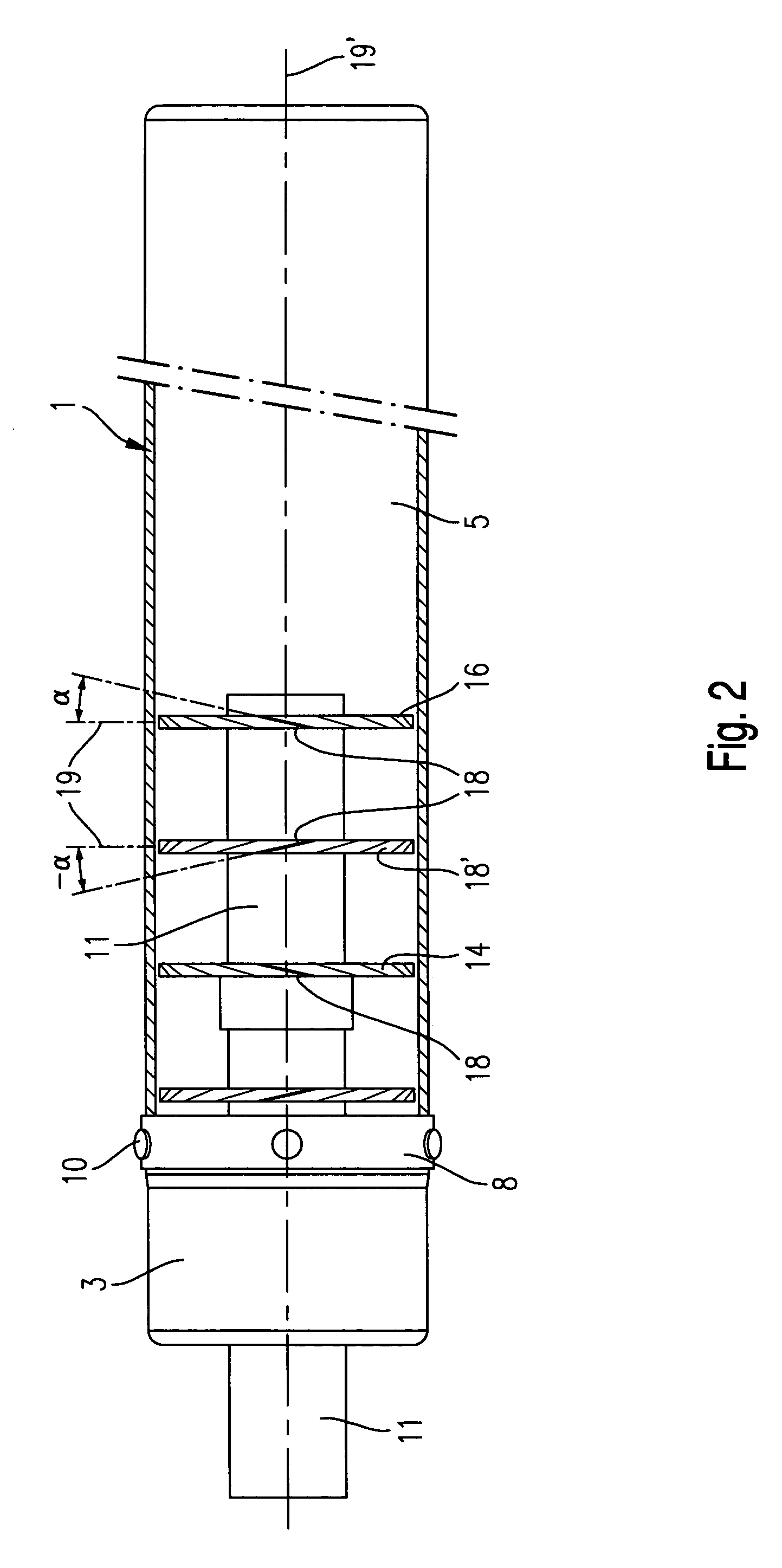
[0017]A muffler 1 comprises a housing 2 having at least one housing part or a housing chamber. The housing 2 is formed by a pot-shaped head element 3, which serves as the housing chamber and has a front end wall 4, and by a cup-shaped housing part 5, which likewise serves as the housing chamber. The housing 2 furthermore has a cylindrical circumferential wall 6 and an end wall 7 at its one end. According to the exemplary embodiments illustrated in FIGS. 1 and 2, a fastening edge 8 having a slightly larger diameter and having fastening holes distributed in the circumferential direction is situated on the head element 3. The housing part 5 is pushed with its open end under the fastening edge 8 of the head element 3 until it makes contact. In the fitted position, the head element 3 and the housing part 5 are connected fixedly to each other. For this purpose, fastening means 10 which extend through the fastening holes are provided. Screw bolts or else rivets are suitable as fastening me...


PUM


Abstract

A muffler has a housing (2) through which exhaust gas flows and which has at least one housing chamber (3, 5) and in which deflecting elements (13 to 16) serving to make the gas swirl are arranged spaced one behind another along a main axis (19′) of the housing in a positionally fixed manner. A disk-shaped body (17′) having guide vanes (18) with slots (18′) therebetween is provided as each deflecting element (13 to 16) and extends over the clear cross section of the housing (2). The guide vanes of adjacent disk-shaped bodies respectively deflect the flow in opposite directions about the main axis (19′) of the housing.

Description

FIELD OF THE INVENTION[0001]The invention relates to a muffler which is intended in particular also for internal combustion engines, having a housing through which a gaseous medium flows and which has at least one housing chamber and in which deflecting elements serving to make the gaseous medium swirl are arranged one behind another along an axis of the housing and in a positionally fixed manner at a distance from one another.BACKGROUND INFORMATION[0002]Mufflers of this type are disclosed, for example, in DE 848 877 and in DE 197 56 468 C1. In the first-mentioned case, locking plates serving as deflecting elements are provided and are inserted into the housing in such a manner that they form labyrinth-like flow paths for the gases without making metallic contact with the housing wall. Furthermore, a muffling material is provided and lines the inner wall of the housing in the form of a lining pad.[0003]In the case of DE 197 56 468, disks, which are similar to fan wheels are arranged...

Claims


Application Information

Patent Timeline
Patent Type & Authority Patents(United States)
IPC IPC(8): F01N1/12F01N1/08
CPCF01N1/088F01N1/084
Inventor WEINHOLD, PETERWINTRICH, PETER
Owner 3W MODELLMOTOREN
Features
  • R&D
  • Intellectual Property
  • Life Sciences
  • Materials
  • Tech Scout
  • Unparalleled Data Quality
  • Higher Quality Content
  • 60% Fewer Hallucinations
Learn More