Cable support systems

a technology of support system and cable, which is applied in the direction of support, cage suspension device, machine support, etc., can solve the problems of inadequate adjustment methods of cable suspension system, inability to provide a simple and easy way of connecting cables, etc., and achieve the effect of restricting the downward movement of cables

Inactive Publication Date: 2006-07-11
DMI CO INC
View PDF21 Cites 12 Cited by
  • Summary
  • Abstract
  • Description
  • Claims
  • Application Information

AI Technical Summary

Benefits of technology

[0005]A clamp for a cable support system is provided that includes a generally “C” shaped clamp body with a threaded fastener threadingly received within one leg of the “C” shaped body to clamp the “C” shaped body onto an overhead beam. A vertical bore through the clamp body receives a cable to be suspended from the overhead beam and there are various devices within the clamp body to restrict the downward vertical movement of the cable relative to the clamp body. One of the arrangements for restricting the downward movement of the cable within the clamp body is to provide a annular shoulder within the bore that cooperates with an oversized end portion on the cable and thereby restricts downward movement of the cable.

Problems solved by technology

The earlier cable suspension systems did not provide adequate methods of adjusting the height of the objects suspended precisely so as to equalize the weight on several cables that might be suspending the same object.
Further, the earlier systems did not provide a simple and easy way of connecting the cables that suspend an object to the overhead structures.

Method used


Image

  • Cable support systems
  • Cable support systems
  • Cable support systems

Examples


second embodiment

[0025]Referring to FIGS. 4 and 5, there is shown a clamp adapted to fix a cable to an overhead beam. The clamp shown generally at 40 has a generally “C” shaped body 44 with a threaded fastener 46 threaded through one leg of the body 44. A lock nut 48 is positioned on the threaded fastener 46 to lock it in place once the threaded fastener 46 clamps the body 44 of clamp 10 onto an overhead beam (not shown). Referring to FIG. 5, there is shown a vertical bore 50 that has an oversized portion 52 at the top of the body of clamp 10. The oversized portion 52 forms an annular shoulder 54 around the top of the smaller vertical bore 50. A cable 56 is shown within the vertical bore 50 and cable 56 has an oversized end 58 which prevents the cable 56 from moving downwardly relative to the clamp body 44 when the oversized end 58 contacts the annular shoulder 54 within the clamp body 44.

third embodiment

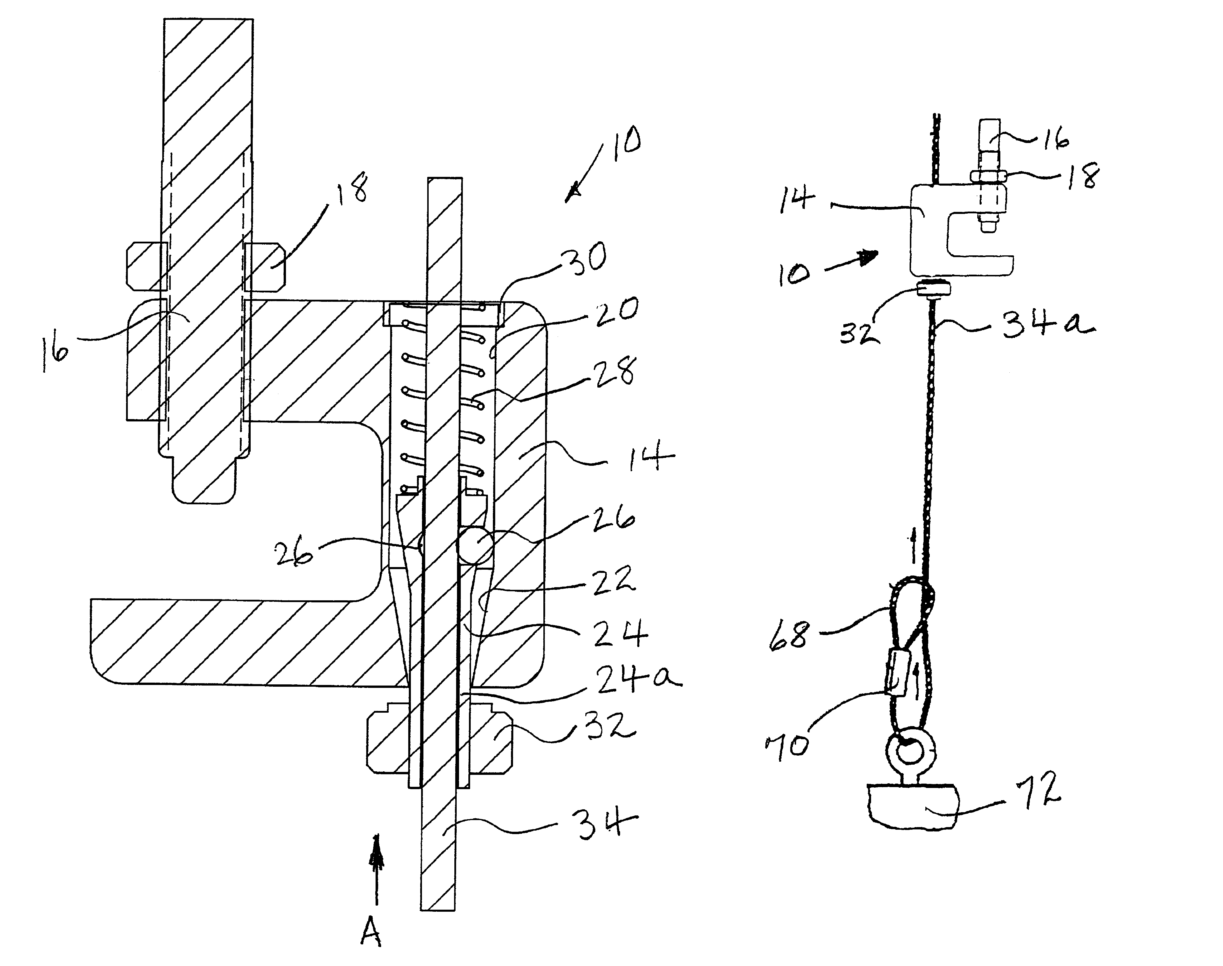
[0026]Referring to FIGS. 6 and 7, there is shown a clamp adapted to fix a cable to an overhead beam. The clamp shown generally at 80 has a generally “C” shaped body 84 with a threaded fastener 86 through one leg of the body 84. A lock nut 88 is positioned on the threaded fastener 86 to lock it in place once the threaded fastener 86 clamps the body 84 of clamp 10 onto an overhead beam (not shown). A vertical bore 90 is provided through the body 84 of clamp 80.

[0027]The vertical bore 90 has a passage 92 communicating with it. Passage 92 extends downwardly at an acute angle to bore 90 and contains a wedge 94 that slides within passage 92. The wedge 94 is urged toward bore 90 by a spring 96 that is retained by a spring cap 98 fixed to the upper end of passage 92. The wedge 94 has release levers 100 fixed to it that extend outwardly from wedge 94 through slots 102 formed into each side of “C” shaped body 84. The slots 102 extend generally parallel to passage 92 and permit the wedge 94 to...


PUM


Abstract

Cable Support Systems for supporting an object at a desired distance below an overhead beam or other overhead structure are provided. Novel clamps for clamping to the overhead structure are fitted to support cables that encircle objects to be supported by the cable support systems. The novel clamps have internal methods to support the cables. The cables are then encircled around the objects and fixed relative to the clamp. The distances between the object and the clamps may be precisely controlled.

Description

BACKGROUND OF THE INVENTION[0001]1. Field of the Invention[0002]This invention relates generally to cable support systems for suspending an object from an overhead structure by means of cables. The cable support systems include novel clamps that clamp to the overhead structure and support the cable that suspends from them to secure the object to be suspended.[0003]2. Prior Art[0004]Various cable support systems have been described and utilized in the prior art to suspend objects from overhead beams. The purposed of such systems is to suspend items such as conduit, heating and air conditioning ducts, piping, and other objects from overhead structures such as beams or roofs. The earlier cable suspension systems did not provide adequate methods of adjusting the height of the objects suspended precisely so as to equalize the weight on several cables that might be suspending the same object. Further, the earlier systems did not provide a simple and easy way of connecting the cables that ...

Claims


Application Information

Patent Timeline
Patent Type & Authority Patents(United States)
IPC IPC(8): F16L3/24E04B9/00F16B2/06F16G11/10
CPCE04B9/006F16B2/065F16L3/24F16G11/10Y10T24/3969Y10T24/3996F16G11/108
Inventor SHUEY, ALAN B.
Owner DMI CO INC
Why Eureka
Try Eureka