One-operation piping-installation fluid pressure apparatus

a fluid pressure apparatus and one-operation technology, applied in the direction of valve housings, hose connections, couplings, etc., can solve the problems of increased man-hours, increased likelihood of improper connection of pipes, and serious operation burden

Inactive Publication Date: 2006-07-11
SMC CORP
View PDF13 Cites 36 Cited by
  • Summary
  • Abstract
  • Description
  • Claims
  • Application Information

AI Technical Summary

Benefits of technology

The purpose of this invention is to make it easy and accurate to connect multiple pipes to a fluid pressure device with just one action. This helps prevent mistakes when setting up equipment.

Problems solved by technology

The technical problem addressed in this patent text relates to the difficulty and time-consuming process of connecting multiple solenoid valves with actuators through pipes. This involves separate mounting of pipe joints and individual fixation of clip components, leading to increased labor costs and potential operational errors. There is also no reduction in the number of steps needed to complete the connections.

Method used


Image

  • One-operation piping-installation fluid pressure apparatus
  • One-operation piping-installation fluid pressure apparatus
  • One-operation piping-installation fluid pressure apparatus

Examples


first embodiment

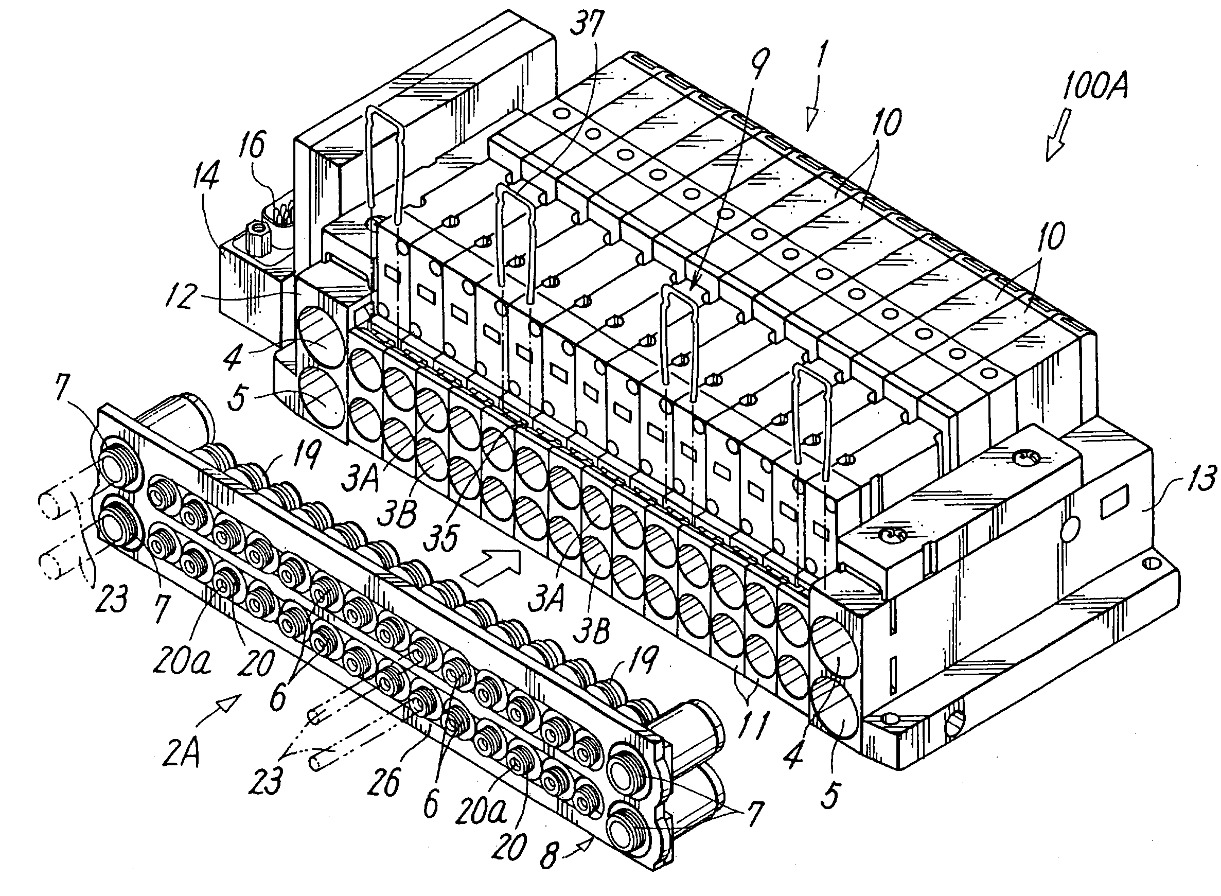
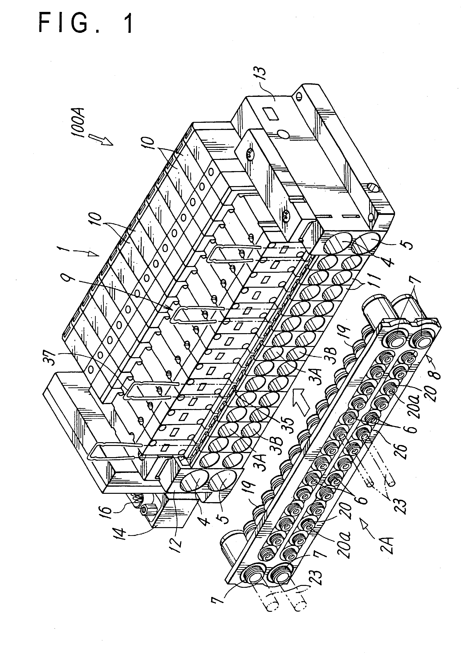
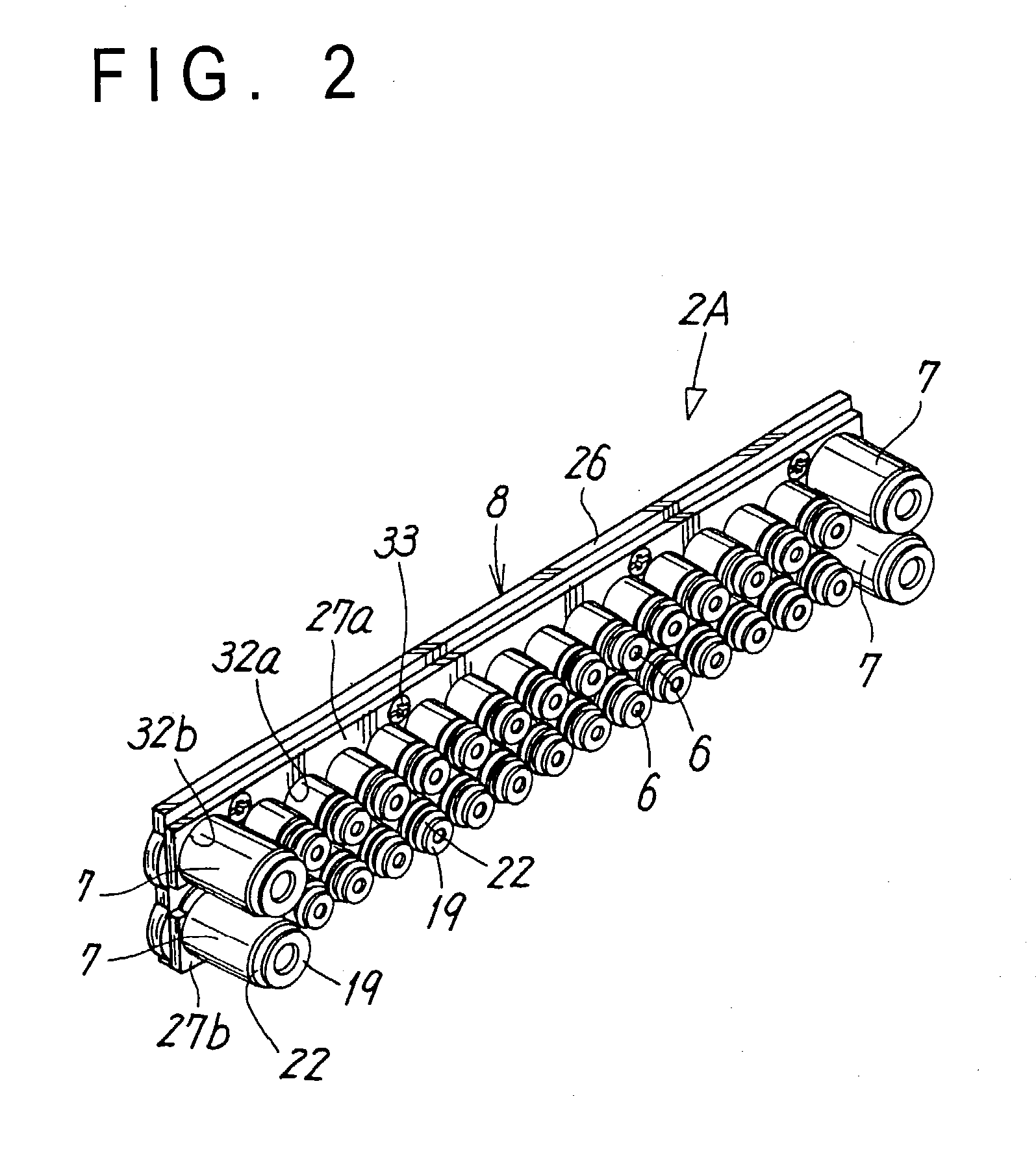
[0036]FIG. 1 shows a one-operation piping-installation fluid pressure apparatus according to the present invention. The fluid apparatus 100A includes a fluid pressure device 1 having a plurality of ports 3A, 3B, 4, and 5 which are provided in a concentrated configuration and open in rows on one end face of the apparatus 100A and to which pipes are connected, a pipe joint assembly 2A formed by retaining a plurality of quick-type pipe joints 6 and 7 in a concentrated configuration and in rows on a set of joint holder 8, and a fixing mechanism 9 for fixing the pipe joint assembly 2A to the fluid pressure device 1 in a connected state.

[0037]The fluid pressure device 1 is in a form of a solenoid valve assembly in which a plurality of solenoid valves 10 and associated members are coupled together. In other words, the respective solenoid valves 10 are individually mounted onto divided manifold blocks 11. By joining the manifold blocks 11 in a lateral width direction and integrally coupling...

fourth embodiment

[0072]In the fourth embodiment, the pipe joints 7 are fitted and retained only in the upper joint retaining holes 30 corresponding to the air supply ports 4 out of the joint retaining holes 30, 30 in the shapes of the single holes at opposite ends of the pipe joint assembly 2A, a cylindrical sleeve 57 is mounted to each of the lower joint retaining holes 30 corresponding to the exhaust ports 5, and the port connecting portion 19 of each the sleeve 57 is connected to the exhaust port 5. However, if the pipes need to be connected also to the exhaust ports 5, the pipe joints 7 are mounted also to the lower joint retaining holes 30.

[0073]Because the structures of the fourth embodiment other than those described above are substantially similar to those of the first embodiment, main similar components are provided with reference numerals similar to those of the first embodiment to omit description of the components.

[0074]Because the fluid pressure device 100D of the fourth embodiment has ...


PUM


Abstract

A fluid pressure apparatus is formed of a fluid pressure device including a plurality of ports opening in rows on its one end face and a pipe joint assembly in which a plurality of quick-type pipe joints are retained by a joint holder in the same arrangement as the respective ports of the fluid pressure device, in rows. Pipes from respective actuators are connected to the respective pipe joints in advance. After the actuators and the fluid pressure device are installed, the respective pipe joints of the pipe joint assembly are inserted into the corresponding ports of the fluid pressure device to thereby connect the pipes to the respective ports of the fluid pressure device by one operation.

Description


Claims


Application Information

Patent Timeline
Owner SMC CORP
Why Eureka
Try Eureka