Liquid ejecting apparatus and controlling unit of liquid ejecting apparatus

a technology of liquid ejecting apparatus and controlling unit, which is applied in the direction of printing, other printing apparatus, etc., can solve the problems of unstable behavior of satellite drop, generated from the longer tail portion, and is difficult to drive the ink-ejecting recording apparatus at a high frequency, so as to facilitate the inability to inhibit the behavior of satellite drop and achieve the effect of stable behavior

Active Publication Date: 2006-07-11
SEIKO EPSON CORP
View PDF22 Cites 16 Cited by
  • Summary
  • Abstract
  • Description
  • Claims
  • Application Information

AI Technical Summary

Benefits of technology

[0020]According to the invention, expansion of the pressure-generating chamber while the third signal-element is applied (outputted) has at least two steps. Thus, if the expansion step of the pressure-generating chamber by the latter step i.e. the second-step element is designed for controlling vibrations of menisci, the voltage level can be adjusted by means of the former step i.e. the first-step element, that is, the design of the first signal-element is not affected. In addition, differently from a case wherein a fourth signal-element is provided as described above, the length of one period of the driving signal can be easily inhibited within a predetermined range.
[0021]Therefore, stableness of behavior of a satellite drop, a suitable ejecting speed of the drop of the liquid and a drive of the liquid ejecting apparatus at a high frequency can be suitably achieved at the same time.

Problems solved by technology

However, when the amplitude of the third signal-element S53 is too large (when the voltage difference Vc2 is too large), the effect of controlling the vibrations is too much.
In the case, as the inventors have found, a column-like ink extending from a meniscus has a longer tail portion, so that behavior (movement) of a satellite drop, which is generated from the longer tail portion, becomes unstable.
To the contrary, if the duration of the first signal-element S51 is increased, one period of the driving signal also becomes longer, so that it becomes difficult to drive the ink-ejecting recording apparatus at a high frequency.

Method used


Image

  • Liquid ejecting apparatus and controlling unit of liquid ejecting apparatus
  • Liquid ejecting apparatus and controlling unit of liquid ejecting apparatus
  • Liquid ejecting apparatus and controlling unit of liquid ejecting apparatus

Examples


Embodiment Construction

[0046]Embodiments of the invention will now be described in more detail with reference to drawings.

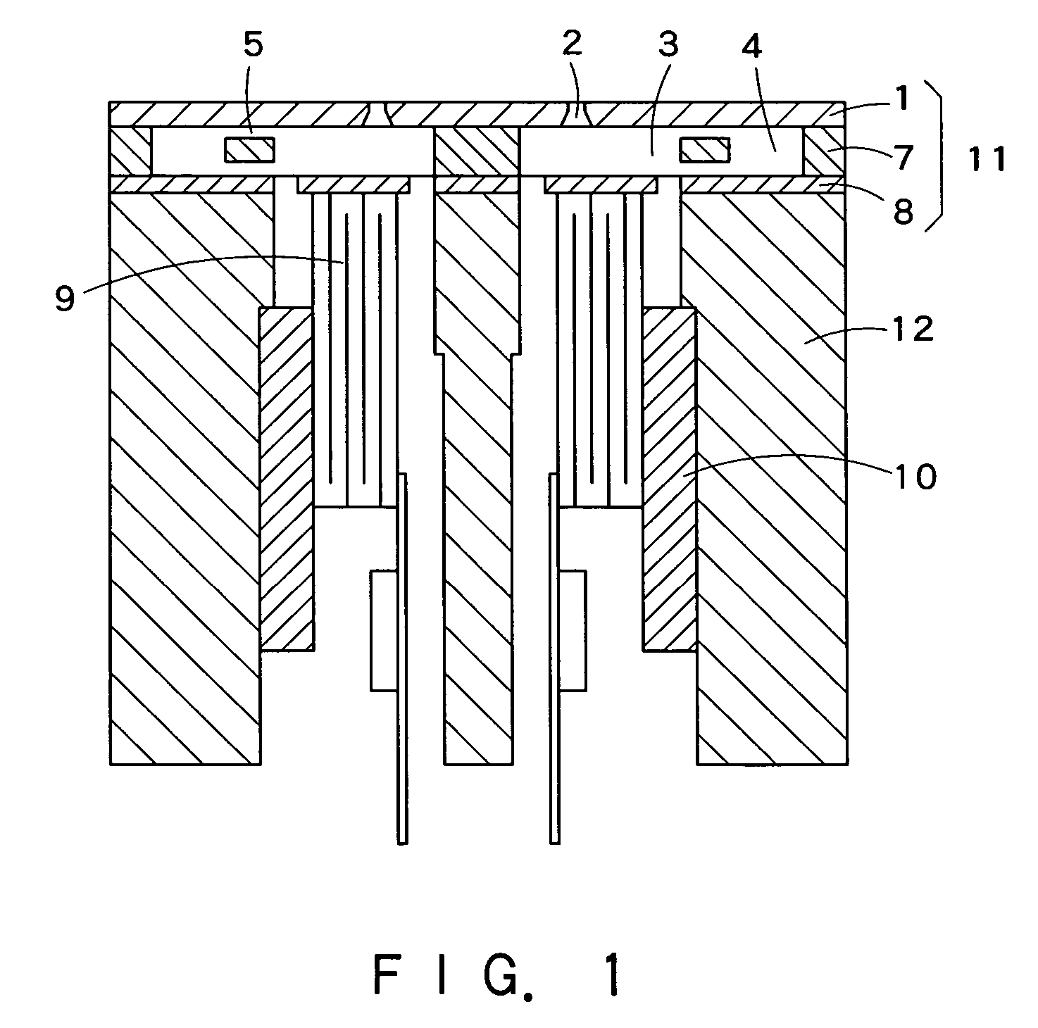
[0047]FIG. 1 shows an example of recording head used in an ink-ejecting recording apparatus (a kind of liquid ejecting apparatus) of an embodiment according to the invention. The recording head shown in FIG. 1 mainly consists of an ink-way unit 11 having nozzles 2 and pressure-generating chambers 3 and a head-case 12 accommodating piezoelectric vibrating members 9. The ink-way unit 11 and the head-case 12 are joined to each other.

[0048]As shown in FIG. 1, the ink-way unit 11 is formed by stacked (layered) nozzle plate 1, way-forming plate 7 and elastic plate 8. The nozzles 2 are formed through the nozzle plate 1. Correspondingly to the respective nozzles 2, the way-forming plate 7 includes a space corresponding to the pressure-generating chambers 3, common ink reservoirs 4 and ink supplying ways 5 connecting the pressure-generating chambers 3 and the common ink reservoirs 4. The elasti...


PUM


Abstract

A liquid ejecting apparatus of the invention includes: a pressure-generating chamber having an inside space whose volume is changeable, into which a liquid is supplied and which is communicated with a nozzle, a resonance frequency of said pressure-generating chamber having a period of Tc; a signal-generating unit that generates a driving signal having: a first signal-element for causing the pressure-generating chamber to expand, a second signal-element for causing the pressure-generating chamber to contract from an expanding state thereof in order to eject a drop of the liquid through the nozzle, and a third signal-element for causing the pressure-generating chamber to expand to an original state before outputting the first signal-element after the drop of the liquid is ejected; and a pressure-generating unit that causes the pressure-generating chamber to expand and contract, based on the driving signal. The third signal-element has: a first-step element for causing the pressure-generating chamber to expand to an intermediate contracting state, which is smaller than the original state before outputting the first signal-element; and a second-step element for causing the pressure-generating chamber of the intermediate contracting state to the original state before outputting the first signal-element. The first-step element and the second-step element are substantially discontinuous in at least one of applying time or inclination.

Description

FIELD OF THE INVENTION[0001]This invention relates to a liquid ejecting apparatus wherein for example a piezoelectric vibrating member is used as an actuator.BACKGROUND OF THE INVENTION[0002]A head member of a liquid ejecting apparatus, such as a recording head of an ink-ejecting recording apparatus, has a pressure-generating chamber which is communicated with a nozzle and which is partly formed by an elastic plate. A movable end of a piezoelectric vibrating member is joined to the elastic plate. The piezoelectric vibrating member can expand and contract. Thus, a volume of the pressure-generating chamber can be changed by causing the piezoelectric vibrating member to expand and contract. As a result, ink can be supplied into the pressure-generating chamber and a drop of the ink can be ejected from the pressure-generating chamber.[0003]As an actuator for driving such a recording head at a high speed, a longitudinal-mode piezoelectric vibrating member is used, which consists of altern...

Claims


Application Information

Patent Timeline
Patent Type & Authority Patents(United States)
IPC IPC(8): B41J29/38B41J2/05B41J2/045
CPCB41J2/04516B41J2/04588B41J2/04581B41J2/04525
Inventor NISHIDA, KEISUKECHANG, JUNHUA
Owner SEIKO EPSON CORP
Why Eureka
Try Eureka