Golf club head and golf club

a golf club and head body technology, applied in the field of golf club head and golf club, can solve the problems of disadvantageous reduction of the strength of the crown portion of the head body, decrease of the distance of the ball flight, and increase the center of gravity, so as to improve the reliability of the golf club head to which the crown part is fixed, and the crown portion can be reinforced.

Inactive Publication Date: 2006-07-11
MIZUNO CORPORATION
View PDF15 Cites 63 Cited by
  • Summary
  • Abstract
  • Description
  • Claims
  • Application Information

AI Technical Summary

Benefits of technology

[0014]As above, by providing the support portion supporting the crown part between the openings, the crown part can be reinforced by the support portion. As a result, the crown portion can be reinforced.
[0023]A golf club according to the present invention includes the golf club head described above. Therefore, a golf club having a golf club head with a reinforced crown portion and high reliability can be obtained.
[0024]According to the present invention, as the support portion and the placing portion capable of supporting the crown part is provided at the opening of the crown portion, the crown portion can be reinforced. Thus, the reliability of the golf club head to which crown part is fixed can be improved.
[0025]Additionally, as the support portion such as the first and second support portions and the X-shaped support portion is provided to the crown portion, in addition to the reinforcement of the crown portion, deflection of the face portion toward the rear side when hitting a ball is allowed to some extent as the support portion extends diagonally on the face portion side. Thus, the bouncing or restitution characteristics can be maintained high. Additionally, provision of such a support portion increases the stiffness of the head and improves the sound thereof when hitting a ball. Further, providing the support portion extending diagonally, twisting distortion of the head when hitting a ball can effectively be suppressed. Thus, when hitting a ball, the direction of the ball flight can be stabilized.

Problems solved by technology

Recently, golf club heads are increasingly manufactured with larger volume, which results in higher center of gravity.
A golf club head with such higher center of gravity may hardly raise a ball high when hitting it and may decrease the distance of the ball flight.
With the golf club head according to Japanese Patent Laying-Open No. 8-196665, as it is simply provided with the through hall penetrating through the head body in a vertical direction, the strength of the crown portion of the head body may disadvantageously be decreased even though the closure plate is fixed to the head body.
While Japanese Utility Model Publication No. 7-4050 describes provision of a plurality of ribs from the back surface of the face portion to the rear end of the club head, the ribs cannot reinforce the crown portion.
Additionally, it does not disclose or suggest to apply the idea disclosed by the publication to the crown portion.
As the ribs reach the back surface of the face portion, the face portion hardly deflects and the distance of the ball flight may disadvantageously be decreased.
With the golf club head according to Japanese Utility Model Laying-Open No. 6-86757, while the strength of the face portion may be improved, reinforcement of the crown portion cannot be achieved.
Additionally, it does not disclose or suggest to apply the idea disclosed by the publication to the crown portion.

Method used


Image

  • Golf club head and golf club
  • Golf club head and golf club
  • Golf club head and golf club

Examples


example 1

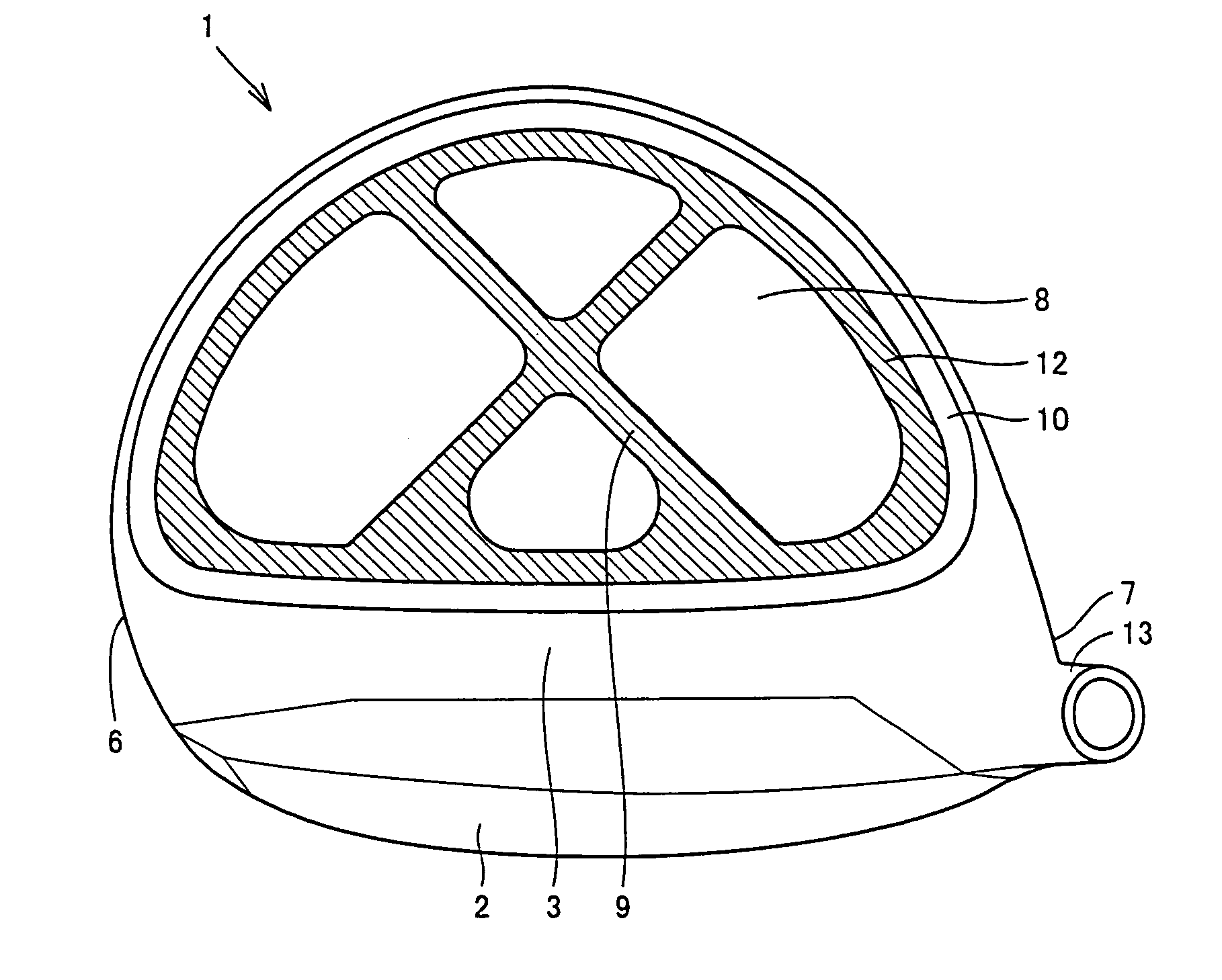
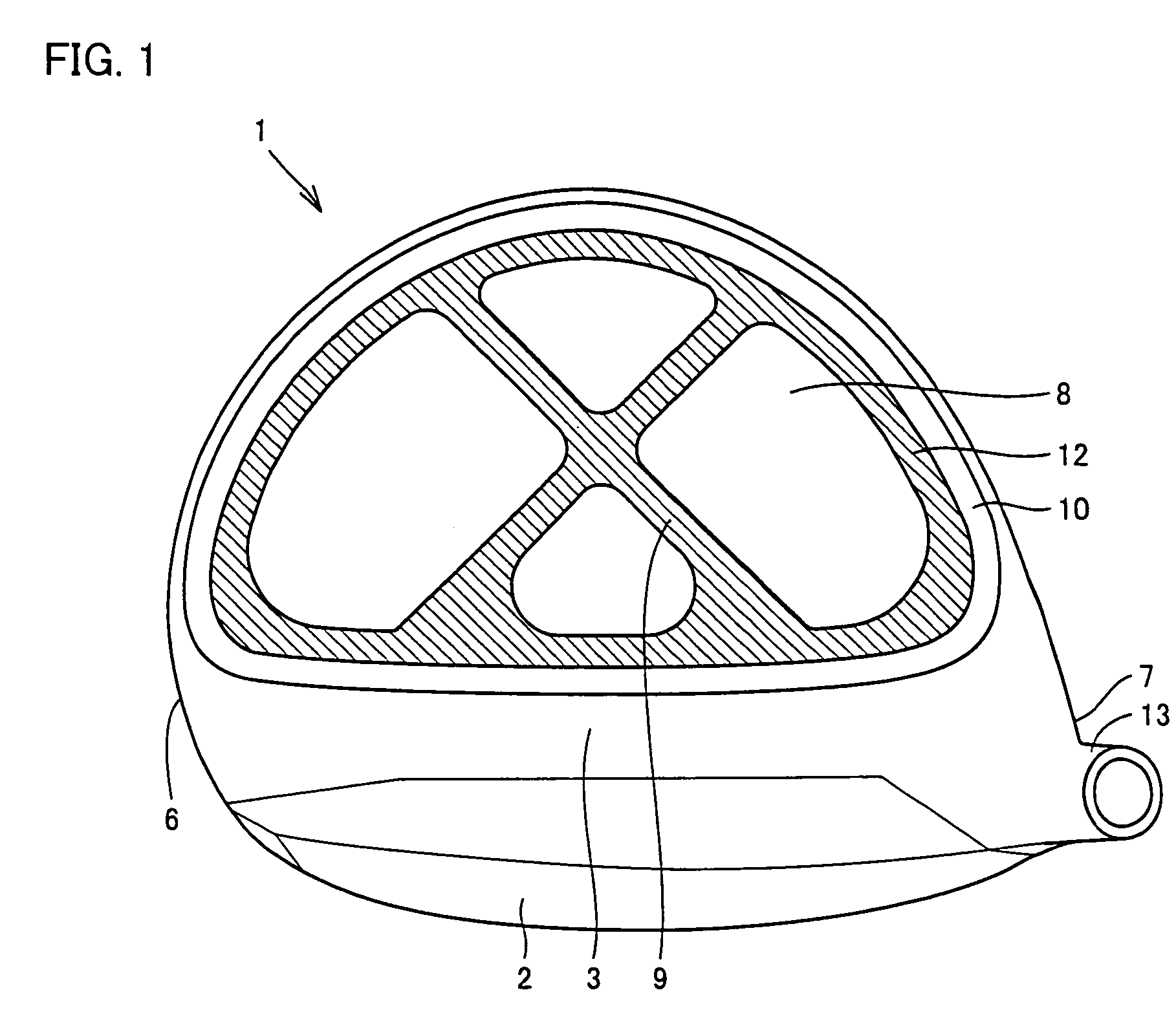
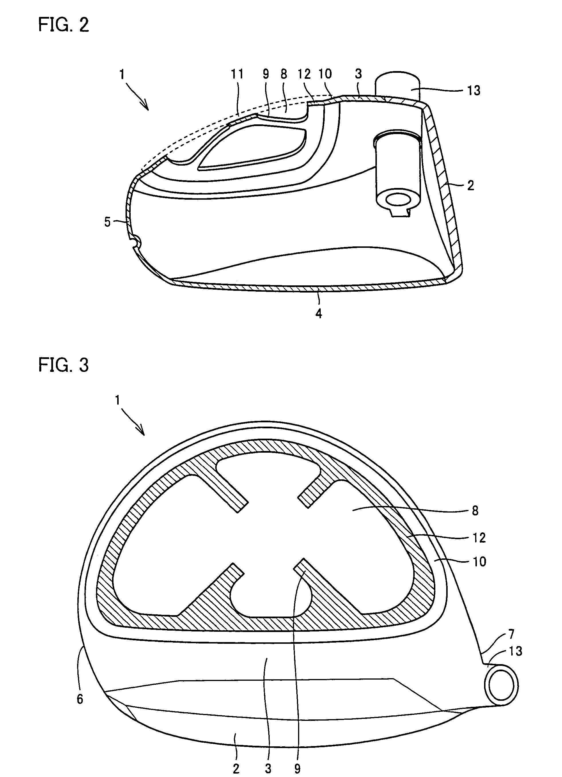
[0074]First, referring to FIGS. 1–3 and FIGS. 6–8, Example 1 of the present invention and the variation thereof will be described. A golf club according to Example 1 includes a golf club head 1 shown in FIG. 1, a shaft and a grip. As the shaft and the grip, well-known components are employed.

[0075]As shown in FIGS. 1 and 2, golf club head 1 includes a face portion 2, a head body, a crown part 11, and a hosel portion 13. Face portion 2 is formed with titanium alloy, and joined with the head body by welding.

[0076]The head body includes a crown portion 3, a sole portion 4, a side portion 5, a toe portion 6, and a heel portion 7, and formed with titanium alloy containing 6 wt % of Al (aluminum) and 4 wt % of V (vanadium). The head body is molded by casting. The thickness of crown portion 3 positioned on the back portion side, which is away from face portion 2, is about 0.9 mm, and the thickness of crown portion 3 positioned on face portion 2 side is about 1.4 mm, the thickness of sole p...

example 2

[0102]Next, Example 2 will be described referring to FIGS. 4 and 5.

[0103]As shown in FIG. 4, support portion 9 may be cross-shaped. Additionally, as shown in FIG. 5, the central portion of support portion 9 may be removed such that support portions 9 are provided separately. In this case also, openings are connected to one another at the central portion of crown portion 3 to be substantially one opening 8. The rest of the structure is basically similar to the example shown in FIG. 4.

example 3

[0104]Next, Example 3 will be described referring to FIG. 9.

[0105]As shown in FIG. 9, according to Example 3 circular openings 14 are provided to support portion 9 and placing portion 12. While substantially the entire of support portion 9 is provided with openings 14 with uniform intervals, placing portion 12 is provided with openings 14 at the portion only on face portion 2 side. The diameter of each opening 14 provided in placing portion 12 is greater than that provided in support portion 9. The rest of the structure is similar to the example shown in FIG. 1.

[0106]In the foregoing, while the embodiment and the examples of the present invention have been described, combinations thereof have also been inherently contemplated.


PUM


Abstract

A golf club head includes: a head body including a crown portion having a plurality of openings, a face portion, a toe portion, a heel portion and a sole portion; a crown part mounted to the head body so as to close the openings, and a support portion provided between the openings for supporting the crown part. The support portion is X-shaped, for example.

Description

[0001]This nonprovisional application is based on Japanese Patent Applications Nos. 2003-087874 and 2004-080632 filed with the Japan Patent Office on Mar. 27, 2003 and Mar. 19, 2004, respectively, the entire contents of which are hereby incorporated by reference.BACKGROUND OF THE INVENTION[0002]1. Field of the Invention[0003]The present invention relates to a golf club head and a golf club having a head body made with metal, and to a golf club head to which a crown part is fixed so as to close crown openings and a golf club having such a head.[0004]2. Description of the Background Art[0005]Recently, golf club heads are increasingly manufactured with larger volume, which results in higher center of gravity. A golf club head with such higher center of gravity may hardly raise a ball high when hitting it and may decrease the distance of the ball flight. Accordingly, various attempts have been made to set the center of gravity of a golf club head lower such that it easily raises the bal...

Claims


Application Information

Patent Timeline
Patent Type & Authority Patents(United States)
IPC IPC(8): A63B53/04A63B53/06A63B102/32
CPCA63B53/0466A63B49/06A63B2053/0416A63B2209/02A63B2053/0437A63B2053/045A63B2053/0408A63B53/0408A63B53/0416A63B53/0437A63B53/045A63B60/52
Inventor NOGUCHI, SHUICHIINUKAI, SHINICHI
Owner MIZUNO CORPORATION
Why Eureka
Try Eureka