Tear-strip seal and tear-seal assembly using a pre-cut tear initialization and a toner hopper, toner cartridge and image forming apparatus using same and method of manufacturing same seal, toner hopper and toner cartridge assembly

a technology of tear-seal and tear-seal assembly, which is applied in the direction of instruments, electrographic process devices, optics, etc., can solve the problems of toner blockage, achieve enhanced tear-seal, prevent toner starvation, and maintain the quality of the image produced

Inactive Publication Date: 2006-07-11
STEVEN BRUCE MICHLIN +1
View PDF23 Cites 9 Cited by
  • Summary
  • Abstract
  • Description
  • Claims
  • Application Information

AI Technical Summary

Benefits of technology

[0012]It is a further object of this invention to provide a seal and seal-insert for the passage from the reservoir which, when the seal is removed from the seal-insert, allows uninterrupted flow of toner from the reservoir to maintain the quality of the image produced.
[0013]Another object of this invention is to design a slotted seal-insert which does not attract toner to its surfaces and cause toner build-up and clogging of the slot. Thus, toner starvation may be prevented.
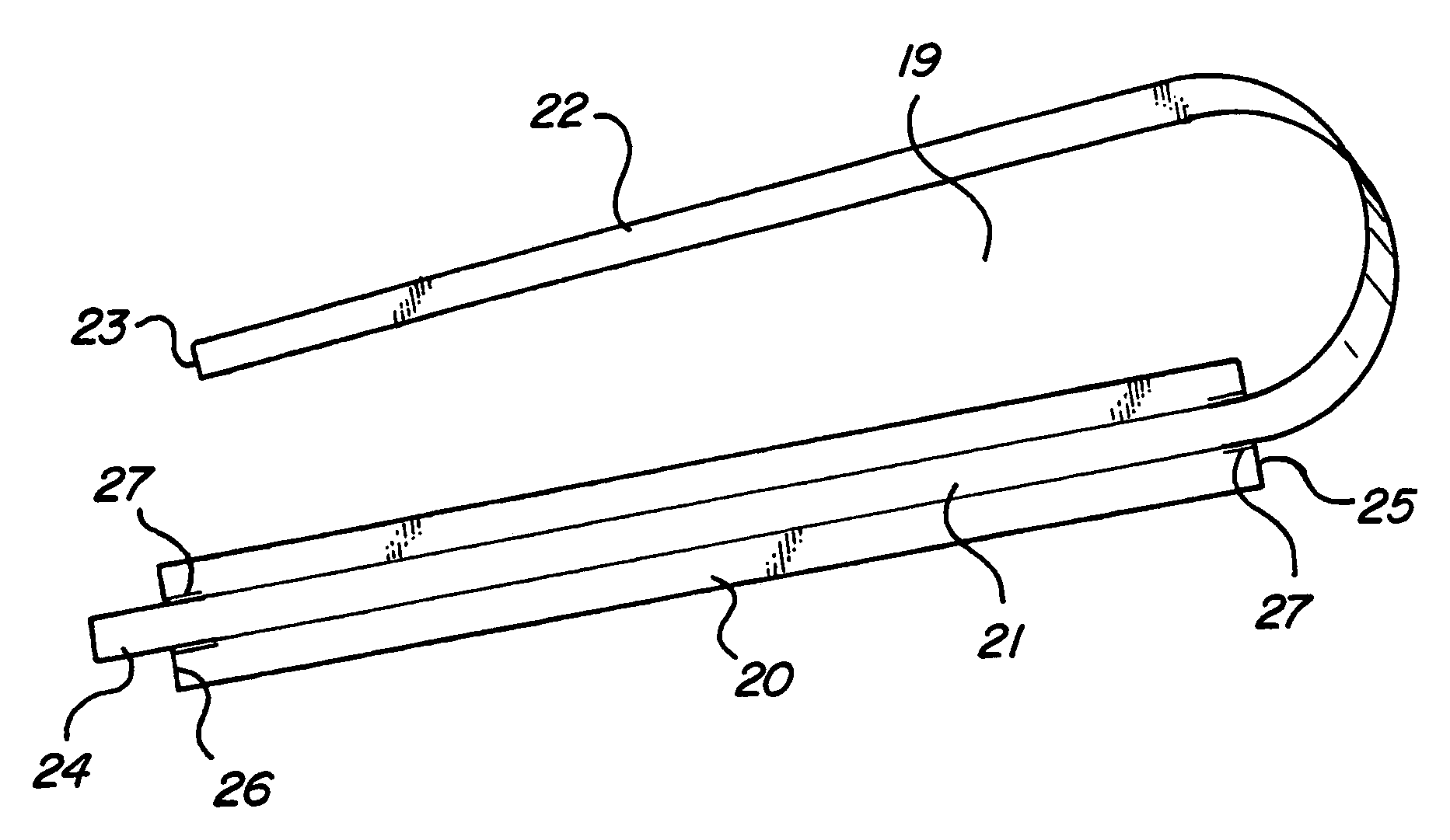
[0014]A still further object of this invention is to provide a tear-guide for the tear-sheet of a tear-seal on a seal-insert which enables the tear-sheet to be torn in a straight line with an even-width rip, opening up a wider opening in the seal-insert or the passage from the reservoir to the feed roller compartment. The tear-guide is used with a seal-insert and tear-seal. Also, with this tear-guide enhanced tear-seal, when the tear is controlled, the opening for toner flow is controlled, and thus when the tear is controlled, a wider than otherwise opening may be made because this torn strip in some cartridges such as LX must be then pulled through a very narrow constriction. By pulling a consistent strip, both the opening may be made wide enough and the even remains of the torn strip may be consistently pulled through the narrow constriction without problems. One such problem in prior technology is premature ripping of the entire tear portion causing a toner blockage.
[0015]A still further object of this invention is to provide an install tail for easy installation, whereby the seal may be easily installed. When the recharger pulls simultaneously on the install tail and the pull strip at the same time, the entire seal may be kept taut, and thus installation is greatly enhanced. With previous technology, many seals get ruined while installing, because there is no means for pulling the seal taut. With the development of the install tail, a very important part of this development, installation is significantly easier, less wastage is made, installation is quicker, and an OEM style seal may be installed in an already joined (non-split) toner hopper which is more difficult to do than when the OEM did it prior to joining. In fact, with this install tail, all the previous tear-seal and other art may be done in a more practical manner as well as the other new art of this invention.
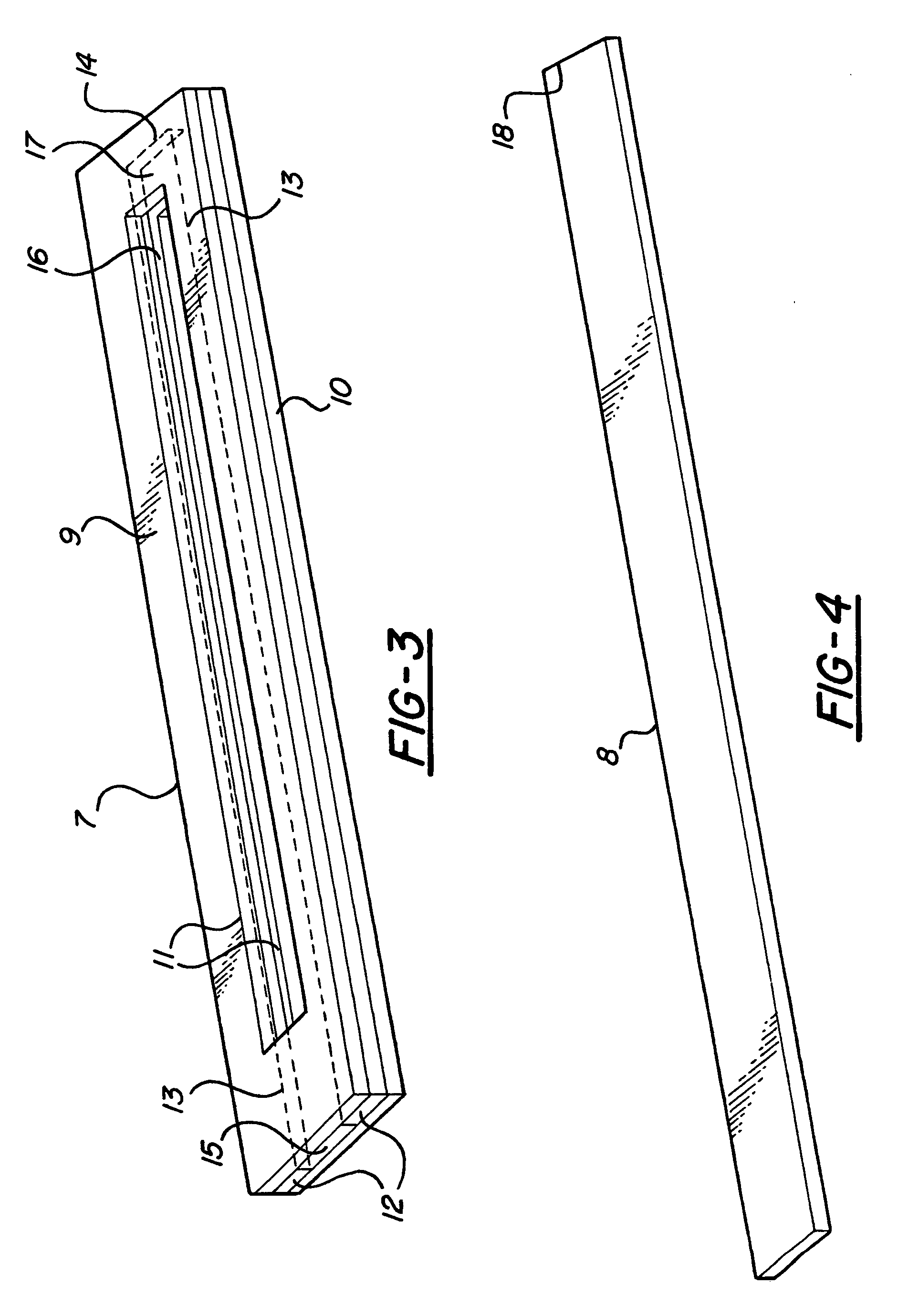
[0016]In carrying out this invention in the illustrative embodiment thereof, a seal-insert is comprised of two rectangular, slotted outer pieces attached together by an inner-layer of two-sided tape. The two-sided tape is configured in a long u-shape such that it has an open end through which a seal is inserted or removed from between the outer pieces to block or open the slot. The seal-insert is attached over the passage from the toner hopper to the feed roller compartment of the toner cartridge assembly. The outer pieces are designed to be antistatic and / or conductive. The outer pieces may be made from antistatic and / or conductive materials or may be more conventional material covered with antistatic and / or conductive sprays, laminates, creams, waxes, coatings or films. Since the seal-insert is grounded through its attachment to the electrically grounded toner hopper, charged toner particles do not stick to the seal-insert and clogging of the slot in the seal-insert and passage from the toner hopper is eliminated. This insures a steady flow of toner to the feed roller compartment and prevents white streaks on the output paper of the imaging machine caused by toner starvation.
[0017]In another embodiment, a conventional tear-seal used with a seal-insert is improved by securing a tear-guide to the tear-sheet of the tear-seal. The tear-guide has a narrower width than the tear-sheet, approximately equal to the width of the slot in the seal-insert. The tear-guide material is chosen for good adhesion to the tear-sheet and good longitudinal strength so it will not break when pulled by the end-user. It may be an adhesive tape. If using an adhesive tape, part of the tear-guide must be kept free from adhesive so it will pull through the slot. This may be done either by not removing some of the tape backing material or by not applying adhesive along the full length of the film tape material. An end of the tear-guide is fed through the opening in the side of the toner hopper, and when pulled will tear the tear-sheet in a straight line and provide an even width rip or opening that will not block toner flow through the toner passage and seal-insert slot. The tear-sheet is also optionally made from or coated or laminated with antistatic and / or conductive material to prevent toner attraction. It may optionally include a stiffener, internal or external, to enable the tear-seal to be easily and efficiently attached to the toner hopper.

Problems solved by technology

One such problem in prior technology is premature ripping of the entire tear portion causing a toner blockage.

Method used


Image

  • Tear-strip seal and tear-seal assembly using a pre-cut tear initialization and a toner hopper, toner cartridge and image forming apparatus using same and method of manufacturing same seal, toner hopper and toner cartridge assembly
  • Tear-strip seal and tear-seal assembly using a pre-cut tear initialization and a toner hopper, toner cartridge and image forming apparatus using same and method of manufacturing same seal, toner hopper and toner cartridge assembly
  • Tear-strip seal and tear-seal assembly using a pre-cut tear initialization and a toner hopper, toner cartridge and image forming apparatus using same and method of manufacturing same seal, toner hopper and toner cartridge assembly

Examples


Embodiment Construction

[0044]This section will begin with a definition of some terms used in this patent application. The purpose of this section is to try to avoid ambiguity in the meaning of any of the terms defined.

Nomenclature

[0045]1. Image Forming Apparatus or Image Forming System or Imaging System: An image forming apparatus is any device that uses dry toner to make an image, including but not limited to a laser printer, copy machine, facsimile machine and microfiche machine. An image forming apparatus uses a dry toner to make the image.[0046]2. Toner cartridge: A toner cartridge is a device that goes into an image forming apparatus and has a photoreceptor, toner hopper and a waste toner hopper. There may be some toner cartridges where the toner hopper and waste toner hopper are connected or have interchanged components. Some toner cartridges use holding pins to attach the toner hopper to the waste toner hopper. Some older cartridges use a case to house the toner hopper and waste toner hopper and th...


PUM


Abstract

An improved seal-insert and seal for a toner hopper as used in toner cartridge assemblies for printers, copiers and facsimile machines. In one embodiment, the seal has two slotted, rectangular outer pieces joined together with slot alignment and joined by an inner layer of two-sided tape. The two-sided tape is made with a long u-shape which does not interfere with the slots in the outer pieces. The open end of the u-shaped tape configuration allows a seal to be inserted or removed from between the outer pieces to close or open the slots. The seal-insert is applied over the passage from the toner hopper. The outer pieces are made from an antistatic and/or a conductive material, such as an aluminum laminate or plastic imprefnated with conductive particles. Alternately, the outer pieces may be made from plastic covered with an antistatic and/or conductive spray or coating. In another embodiment, a tear-seal is made from antistatic and/or conductive material, and is provided with a tear-guide secured to and under the tear-sheet. The tear-guide has a width smaller than the tear-sheet and slightly smaller than the slot of the seal-insert. When the tear-guide is pulled by the enduser, the tear-guide will rip the tear-sheet in a straight line, providing an opening with an even width that will not block toner flow.

Description

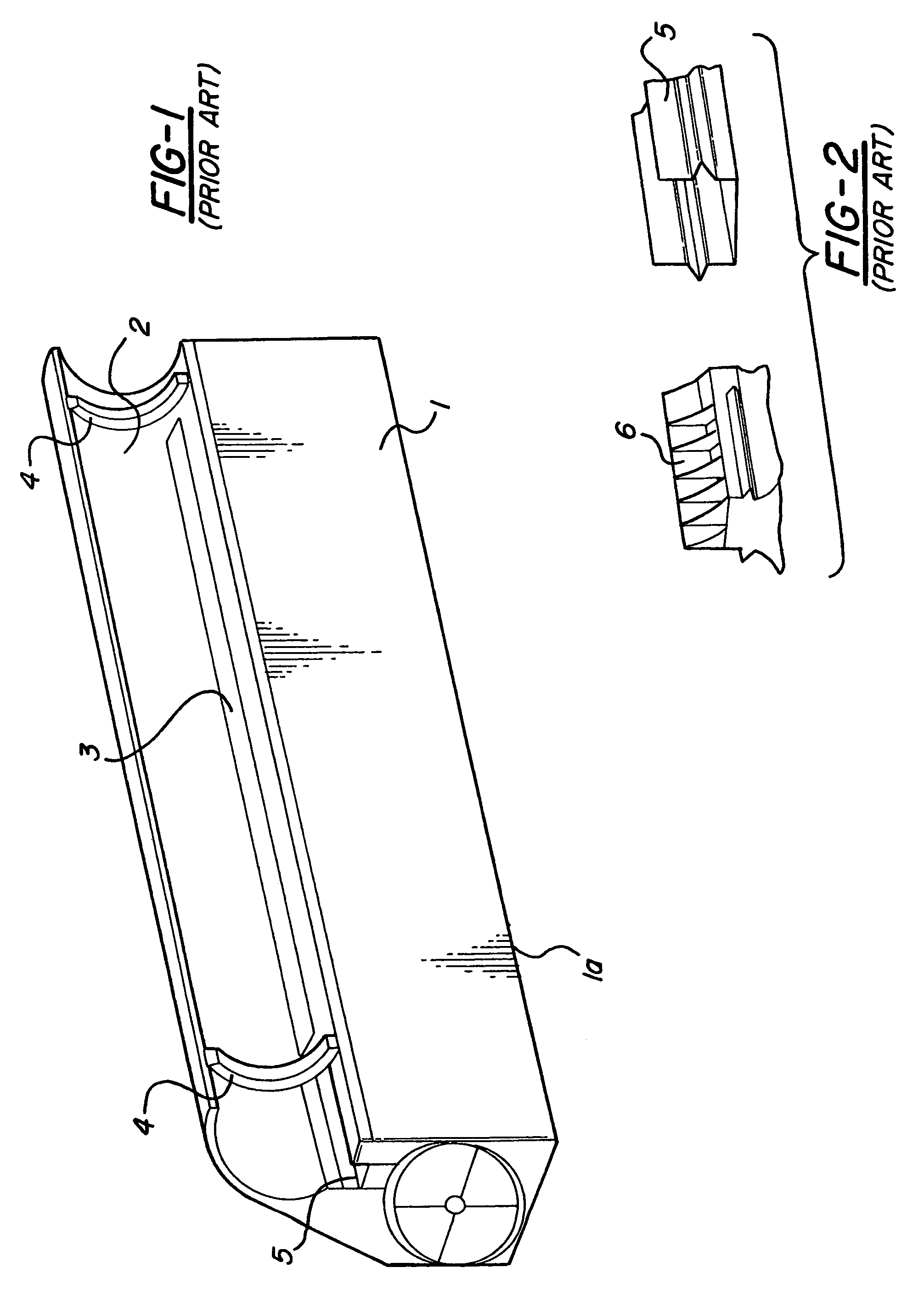
BACKGROUND OF THE INVENTION[0001]This patent application is a continuation of patent Ser. No. 08 / 370,968 filed on Jan. 10, 1995 now U.S. Pat. No. 6,552,780.[0002]This invention relates to an apparatus for allowing the refilling and sealing of a toner hopper used in toner cartridge assemblies for dry toner imaging machines such as printers, copiers and facsimile machines.[0003]The use of “throw-away” type toner cartridge assemblies is common in the dry toner imaging industry. The user of the printer, copier or facsimile machine must buy a new toner cartridge assembly from the manufacturer when the original assembly is depleted of toner. Toner cartridge assemblies are expensive and their disposal is a waste of good components. This expense and waste has created a need for remanufacturing and sealing used toner cartridge assemblies for shipment to the user.[0004]The manufacturers seal the toner hopper assemblies of the new toner cartridge assemblies at their manufacturing location, and...

Claims


Application Information

Patent Timeline
Patent Type & Authority Patents(United States)
IPC IPC(8): G03G15/00G03G15/08
CPCG03G15/0894G03G2215/00987
Inventor MICHLIN, STEVEN BRUCEANDERSON, JEFFREY BYRON
Owner STEVEN BRUCE MICHLIN
Why Eureka
Try Eureka