Method for the production of a shaft-hub connection

a technology of shaft and hub, which is applied in the direction of couplings, manufacturing tools, and gearings, etc., can solve the problems of increasing the cycle time during the making of the connection, affecting the quality of the connection, so as to avoid any damage to the toothings which is associated with this, and the production method is simple and cost-effective

Inactive Publication Date: 2006-07-18
DAIMLER AG
View PDF19 Cites 6 Cited by
  • Summary
  • Abstract
  • Description
  • Claims
  • Application Information

AI Technical Summary

Benefits of technology

[0005]By virtue of the invention, the shaft can always be pushed into the exact axial assembly position in a simple way, since, in this first step for making the assembled connection, there is full play between the shaft and hub and no jamming or even pressing occurs when the shaft is being pushed through. As an accompaniment, any damage to the toothings which is associated with this is also avoided. Narrow manufacturing tolerances of the toothings of the shaft and hub and of their axial and circumferential dimensions no longer play any part in the reliability of the production process, so that, on the one hand, cost-effective materials, even without any heat treatment, and simple production methods can be used for the hub and the shaft and, on the other hand, the particularly considerable outlay in terms of apparatus and time for fulfilling required narrow manufacturing tolerances in the assembled connection may be dispensed with. Thus, overall, the reproducibility of the assembled connection is fully ensured. Furthermore, by a hollow shaft being used specifically for the method, there is a weight saving in the assembled connection and therefore material resources are utilized more effectively. As a result of the circumferential pressure against the hub due to the widening of the hollow shaft, high non-positive and positive locking between shaft and hub is achieved, which is fully compatible with the dynamic loads. That is to say, no fit clearance occurs during the dynamic load, and there is also no increase in the clearance, and therefore direct torque transmission, without any time delay, is ensured. The fit clearance is prevented by the non-positive component of the connection on account of the elastic reformation of the hub. In addition, as a result of this non-positive or frictional component, a high resistance force against axial displacement of the hub on the shaft after assembly is generated. Moreover, a high long-term durability of the assembled connection is achieved, since the toothing is not shaken during the operating time. The disturbing rattling noises associated with fit clearance when the teeth knock against one another also do not arise. Process management during assembly is also simplified, the shaft / hub connection requiring only two work steps, to be precise the pushing of the shaft into the hub and the widening of the shaft.

Problems solved by technology

However, before the shaft is pushed into the hub, the internal toothing of the wheel hub is upset on an end-face portion, so that the tooth spaces of the internal toothing on this portion have a smaller width in relation to the remaining part of the hub.
In this case, the internal toothing of the portion having the smaller space width and also the external toothing are subjected to very high mechanical stress, with the result that damage to the toothings when the shaft is being pressed through may occur, this being, in particular, against the background of the inclusion of the manufacturing tolerances of the individual parts (shaft, hub).
Furthermore, the abovementioned upsetting, on the one hand, is an additional work step, thus increasing the cycle time during the making of the connection, and, on the other hand, can be reproduced only with difficulty and requires highly accurate and therefore complicated process management.
Moreover, the problem of axial tolerances of the shaft has a major bearing, since, after the shaft has been pressed through the hub, positioning on the latter to achieve the desired exact relative position of the shaft in relation to the hub is virtually impossible to correct.

Method used


Image

  • Method for the production of a shaft-hub connection
  • Method for the production of a shaft-hub connection
  • Method for the production of a shaft-hub connection

Examples


Embodiment Construction

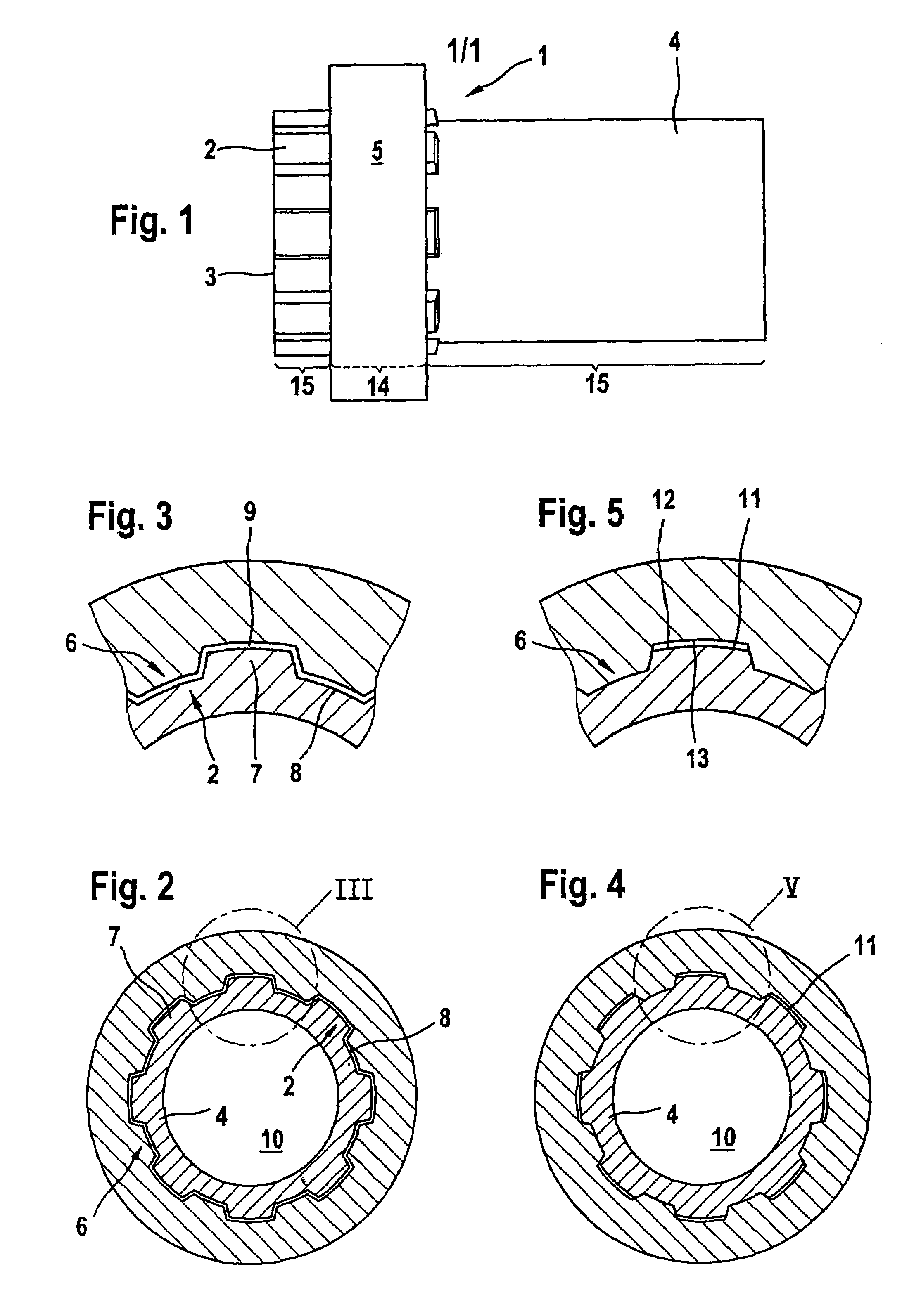
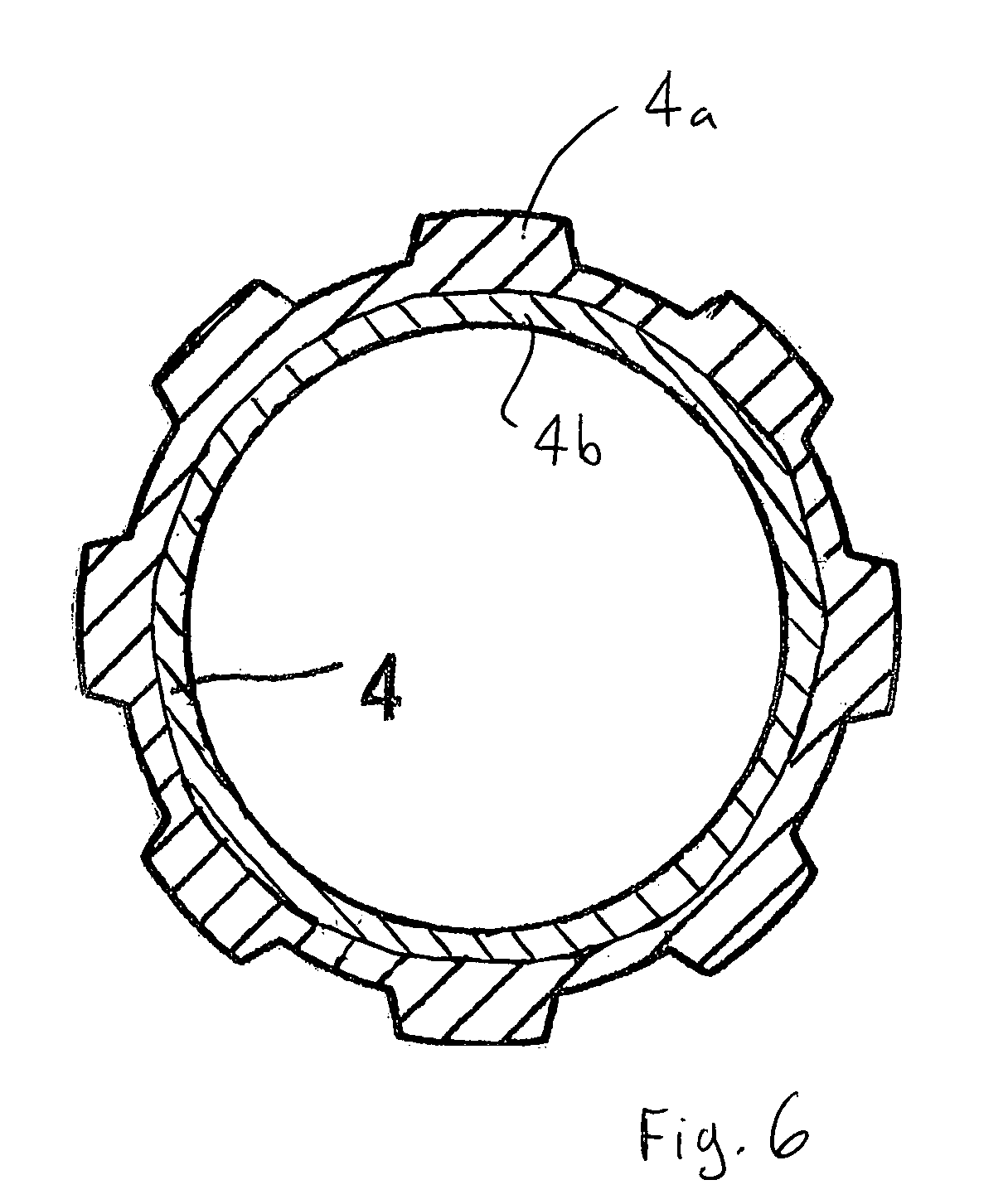
[0013]FIG. 1 illustrates a shaft / hub connection 1, in which an end portion 3 of a hollow shaft 4, the end portion being provided with an external toothing 2, projects through a hub 5. The hollow shaft 4 may be designed as a toothed shaft or, as here in the exemplary embodiment, as a splined shaft. The splined shaft can be produced in a simple way, for example, by drawing a tube or by milling that portion 3 of the hollow shaft 4 which is intended for the formation of the toothing. The corresponding internal toothing 6 of the hub 5 can be generated by reaming or else by milling. Referring to FIG. 6, is also conceivable for the hollow shaft 4 to be formed from two separate structural parts, a toothed rim 4a and a smooth-cylindrical tube 4b, the toothed rim 4a which forms the external toothing 2 of the hollow shaft 4 being pushed onto the tube into the desired axial assembly position and subsequently being fastened unreleasably to the tube, for example, by welding or by a partial wideni...


PUM

PropertyMeasurementUnit
pressureaaaaaaaaaa
pressureaaaaaaaaaa
dimensionsaaaaaaaaaa

Abstract

A toothed or splined shaft having an external toothing is pushed with clearance into an internal toothing of a hub, tooth to space, and the external toothing of the shaft is pressed together with the internal toothing of the hub. In the push-in position of the shaft, the latter is deformed plastically out of a cavity of the shaft in a radial circumferential widening operation and, so as to provide freedom from clearance between the spaces of the external toothing of the shaft and the internal toothing of the hub, the internal toothing engaging into the external toothing is pressed against the hub in such a way that the hub is deformed elastically and a press fit between the shaft and the hub is produced.

Description

BACKGROND AND SUMMARY OF THE INVENTION[0001]This invention relates to a method for making a shaft / hub connection.[0002]A generic method is known from German publication DE 43 02 726 A1. In this case, in a first step to make the assembled connection, the hub and the shaft are designed in such a way that the internal toothing of the hub and the external toothing of the shaft are coordinated with one another in terms of their dimensions, so that, when the shaft is pushed into the hub, a clearance fit is obtained between the two hub / shaft assembled parts. However, before the shaft is pushed into the hub, the internal toothing of the wheel hub is upset on an end-face portion, so that the tooth spaces of the internal toothing on this portion have a smaller width in relation to the remaining part of the hub. The shaft is then slipped into the hub portion having the original space width and is subsequently pressed through the hub portion provided with the smaller space width. In this case, ...

Claims


Application Information

Patent Timeline
Patent Type & Authority Patents(United States)
IPC IPC(8): B21D39/00F16D1/06F16D1/072
CPCF16D1/072F16D2001/103Y10T74/19651Y10T29/49805Y10T29/49915Y10T29/49938Y10T29/49911Y10T29/49465Y10T29/49467Y10T29/4994
Inventor HARMS, TORSTENKNUEDEL, JUERGEN
Owner DAIMLER AG
Why Eureka
Try Eureka