Firing system for a firearm

a firing system and firearm technology, applied in the field of firing systems for firearms, can solve the problems of preventing the firing of the weapon, incapacitate the ignition system, and expose the ignition system to the elements

Inactive Publication Date: 2006-07-18
KNIGHT RIFLE +1
View PDF24 Cites 15 Cited by
  • Summary
  • Abstract
  • Description
  • Claims
  • Application Information

AI Technical Summary

Benefits of technology

[0017]Advantageously, in a preferred example of this invention, an improved action is provided for a firearm having a grip, a receiver, a forwardly extending barrel and a trigger assembly. The improvement comprises a frame and a hammer pivotably coupled to the frame. Means are provided on a carriage for releasably engaging the hammer when the carriage is pivoted a first direction, and for releasing the hammer when the carriage is pivoted in an...

Problems solved by technology

One drawback associated with typical muzzleloading ignition systems is the exposure of the ignition system to the elements.
Moisture and debris can incapacitate an ignition system, while wind and other environmental elements contacting the ignition system can dislodge the ignition system, preventing firing of the weapon.
Another drawback associated with the prior art is the shock, smoke and debris expelled from the ignition system being directed upward toward the shooter's face.
Not only does such debris cause a hazard to the eyes of the shooter, but such debris can also cause the shooter to develop a flinch, as well as briefly obstruct the shooter's view of the target.
While firing mechanisms such as that d...

Method used


Image

  • Firing system for a firearm
  • Firing system for a firearm
  • Firing system for a firearm

Examples


Embodiment Construction

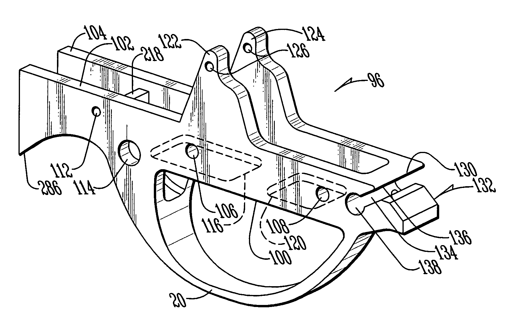
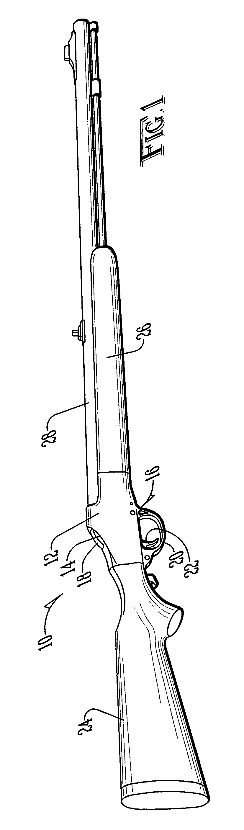
[0038]Referring to FIG. 1, a firearm (10) according to this invention is shown with a frame (12), preferably constructed of stainless steel or similar material. The frame (12) is preferably provided with an upper aperture (14) and a lower aperture (16). Extending through the upper aperture (14) is a portion of the carriage assembly (18), described in more detail below. Extending through the lower aperture (16) is the trigger guard (20) and trigger (22). As shown in FIG. 1, the frame (12) connects a grip, such as a rear stock (24) to the front stock (26) and barrel (28).

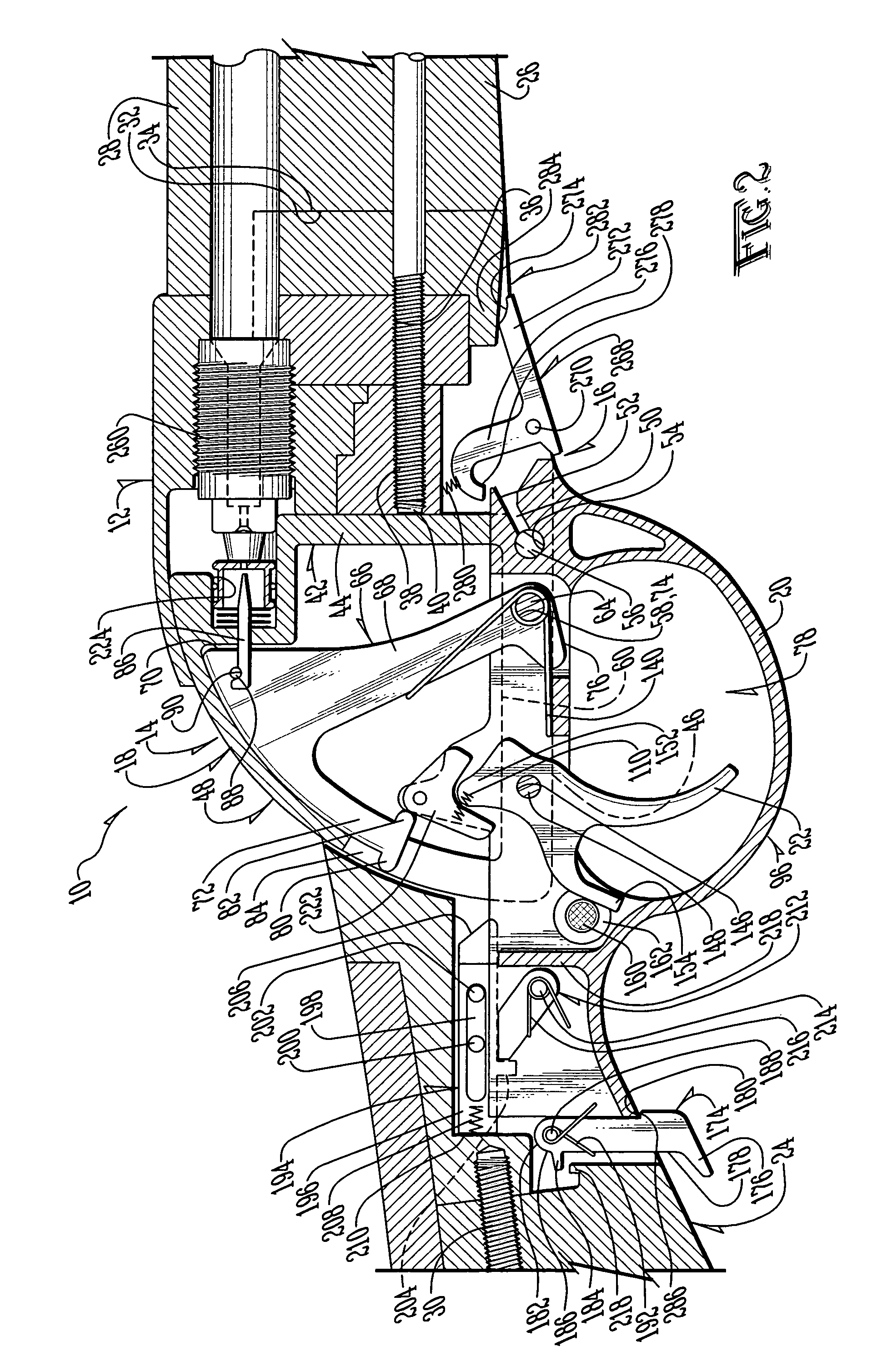
[0039]As shown in FIG. 2, the rear stock (24) is coupled to the frame (12) by a rear stock retaining screw (30) in a manner such as that known in the art. Similarly, the front stock (26) is provided with a slot (32), configured to receive a lug (34) constructed of stainless steel, with a rectangular cross-section. The lug (34) is welded or otherwise secured directly to the barrel (28). The lug (34) is provided with a ...


PUM


Abstract

An improved action for a muzzleloading firearm which allows loading an ignition system from above, and completely releasing the action from below. The system covers the ignition system during firing to shield the user and the line of sight. The action may be removed in the field for inspection, cleaning or repair, without the need for tools.

Description

BACKGROUND OF THE INVENTION[0001]1. Field of the Invention[0002]The present invention relates in general to a firing system for a firearm and, more particularly, to a firing system for a muzzleloading firearm.[0003]2. Description of the Prior Art[0004]It is known in the art of muzzleloading firearms to provide a nipple upon which is positioned a percussion cap used to ignite a power charge, thereby discharging a projectile. It is also known in the art to provide flint or primers to ignite the powder charge. One drawback associated with typical muzzleloading ignition systems is the exposure of the ignition system to the elements. Moisture and debris can incapacitate an ignition system, while wind and other environmental elements contacting the ignition system can dislodge the ignition system, preventing firing of the weapon.[0005]Another drawback associated with the prior art is the shock, smoke and debris expelled from the ignition system being directed upward toward the shooter's f...

Claims


Application Information

Patent Timeline
IPC IPC(8): F41C7/00B05D1/18C07D207/404F41C9/08G01N33/543
CPCF41C9/08
Inventor HENGSTENBERG, ERICCARR, HOWARD D.WINTER, STEVEN J.VOGEL, JERALD M.DAYAL, VINAY
Owner KNIGHT RIFLE
Why Eureka
Try Eureka