Screw having non-strip drive recess and driver bit for use with the screw

a technology of screw and drive recess, which is applied in the direction of screwdrivers, screws, fastening means, etc., can solve the problems of reducing the strength per unit area applied to the engaging wall, and the drive recess is not easily stripped off, so as to achieve stable and secure transmission of driving force

Active Publication Date: 2006-07-18
NITTO SEIKO KO
View PDF19 Cites 24 Cited by
  • Summary
  • Abstract
  • Description
  • Claims
  • Application Information

AI Technical Summary

Benefits of technology

[0014]According to the stated construction, the area of the engaging walls of each engaging groove, which receive rotative driving force applied by a driver bit, can be enlarged without making the drive recess deep. As the area of the engaging walls are enlarged, the suppress strength per unit area applied to the engaging walls is reduced, and therefore the drive recess is not easily stripped off even when a strong driving force is applied by the driver bit.
[0019]According to the stated construction, the contacting area between the drive recess and the engaging blades of the driver bit can be surely enlarged, and this ensures stable and secure transmission of the driving force.

Problems solved by technology

As the area of the engaging walls are enlarged, the suppress strength per unit area applied to the engaging walls is reduced, and therefore the drive recess is not easily stripped off even when a strong driving force is applied by the driver bit.

Method used


Image

  • Screw having non-strip drive recess and driver bit for use with the screw
  • Screw having non-strip drive recess and driver bit for use with the screw
  • Screw having non-strip drive recess and driver bit for use with the screw

Examples


first embodiment

The First Embodiment

(1) Construction of a Screw

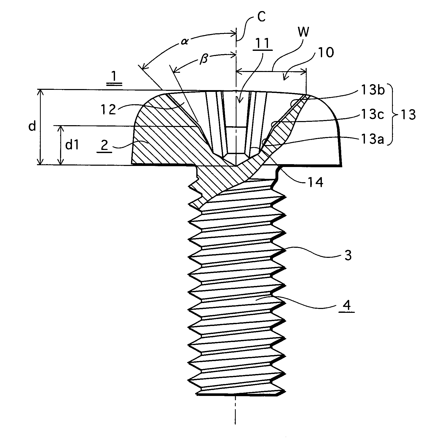
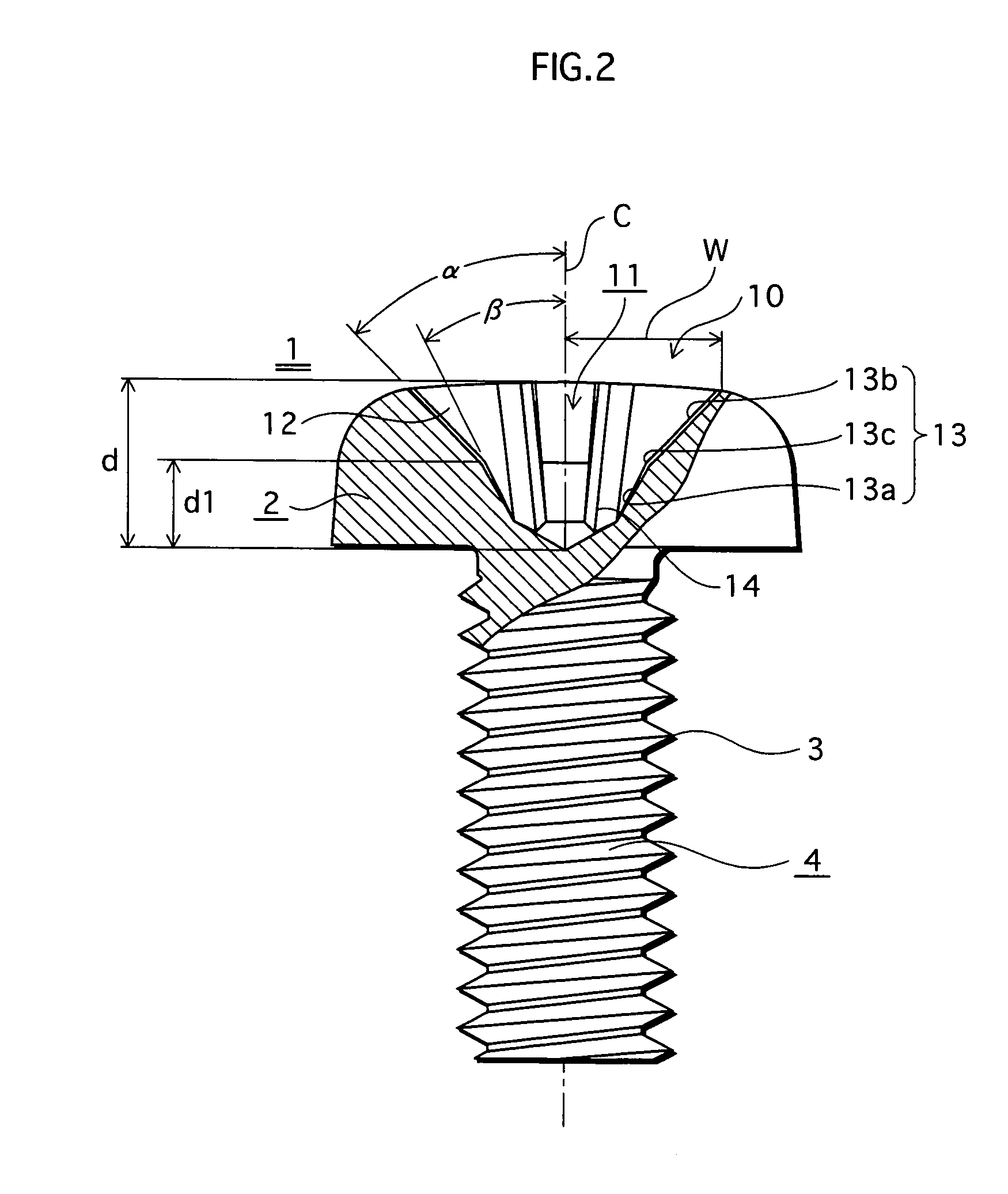
[0031]FIG. 2 is a cutaway view showing a shape of a portion of a drive recess of a screw 1 according to the first embodiment of the present invention, and FIG. 3 is an enlarged plan view of a screw head 2 of the screw 1 in FIG. 2.

[0032]As FIG. 2 shows, the screw consists of the screw head 2 and a screw shank 4 on which threads 3 are formed. The screw shank 4 is integrally formed with the screw head 2. The screw head 2 of the screw 1 has a drive recess 10, with which a drive head 22 of a driver bit 20 shown in FIG. 4 described later is to be engaged.

[0033]The drive recess 10 is radiated from an axis C of the screw 1 as an enlarged plan view in FIG. 3 shows, and consists of four engaging grooves 11 disposed equiangularly and a central hole 15 formed around the axis C.

[0034]Note that although four engaging grooves are formed so as to be in cross shape in this embodiment, the number of the engaging grooves is not limited to four, and any nu...

second embodiment

The Second Embodiment

[0057]The following is a description of a screw according to the second embodiment of the present invention.

[0058]A screw 30 according to this embodiment has a thinner screw head than that of the screw 1 of the first embodiment, and this type of screw is called “a thin-head screw”.

[0059]FIG. 7 is a cutaway front view of the screw 30, and FIG. 8 is a plan view of the screw head of the screw 30. In both figures, constituents numbered in the same manner as in FIG. 2 respectively represent the same constituents as those in FIG. 2.

[0060]As FIG. 7 shows, a reinforcing part 5, which is in shape of an inverted cone having a major part on the side near the screw head 2, is formed between the screw head 2 and the screw shank 4 of the screw 30. The reinforcing part 5 reinforces the neck portion of the screw 30 because the drive recess 10 of the screw head 2 is formed in such a manner as to reach the screw shank 4. A height “h” of the reinforcing part 5 in the direction of ...


PUM


Abstract

The present invention provides a screw, comprising a screw head having a drive recess and a screw shank having threads and being integrally formed with the screw head, wherein the drive recess includes a plurality of engaging grooves equiangularly radiating from an axis of the screw in plan view, a bottom face of each engaging groove having a steep slope, which is near to the screw shank, and a gentle slope, which is far from the screw shank, for enlarging the engaging area of the engaging grooves.

Description

[0001]This application is based on application NO. 2003-155321 filed in Japan, the content of which is hereby incorporated by reference.BACKGROUND OF THE INVENTION[0002](1) Field of the Invention[0003]The present invention relates to a screw having a drive recess that is not easily stripped off when a driver bit is engaged with the drive recess and strong driving force is applied to the recess. Also, the present invention relates to a driver bit for use with the screw.[0004](2) Description of the Related Art[0005]A screw having a drive recess, which consists of a screw head with the drive recess and a screw shank with threads, is used in every field as a fastening part for assembling a product, attaching parts to a workpiece and so on.[0006]FIG. 1 is a cutaway view showing a shape of a drive recess 110 of a conventional screw 101 having a drive recess (a screw having a drive recess is hereinafter simply called the “screw”).[0007]The drive recess 110, which is substantially in cross ...

Claims


Application Information

Patent Timeline
Patent Type & Authority Patents(United States)
IPC IPC(8): B25B23/00B25B15/00F16B23/00
CPCF16B23/0023
Inventor TOYOOKA, TOSHIMASAHAMANO, SHINICHI
Owner NITTO SEIKO KO
Why Eureka
Try Eureka