Multi-layered trap ballistic armor

Inactive Publication Date: 2006-07-18
SOUTHWEST RES INST +1
View PDF24 Cites 40 Cited by
  • Summary
  • Abstract
  • Description
  • Claims
  • Application Information

AI Technical Summary

Benefits of technology

[0008]As described above, some armor systems are designed to use the primary armor layer to initiate rotation, or “tumbling” about the incoming velocity vector of the projectile. Rotation of the ballistic projectile relies on the use of asymmetric force to initiate turning, and requires space between the initiating element and some type of backup element t

Problems solved by technology

In other armor systems, a ceramic-faced armor operates to blunt the point and shorten the length o

Method used


Image

  • Multi-layered trap ballistic armor
  • Multi-layered trap ballistic armor
  • Multi-layered trap ballistic armor

Examples


Embodiment Construction

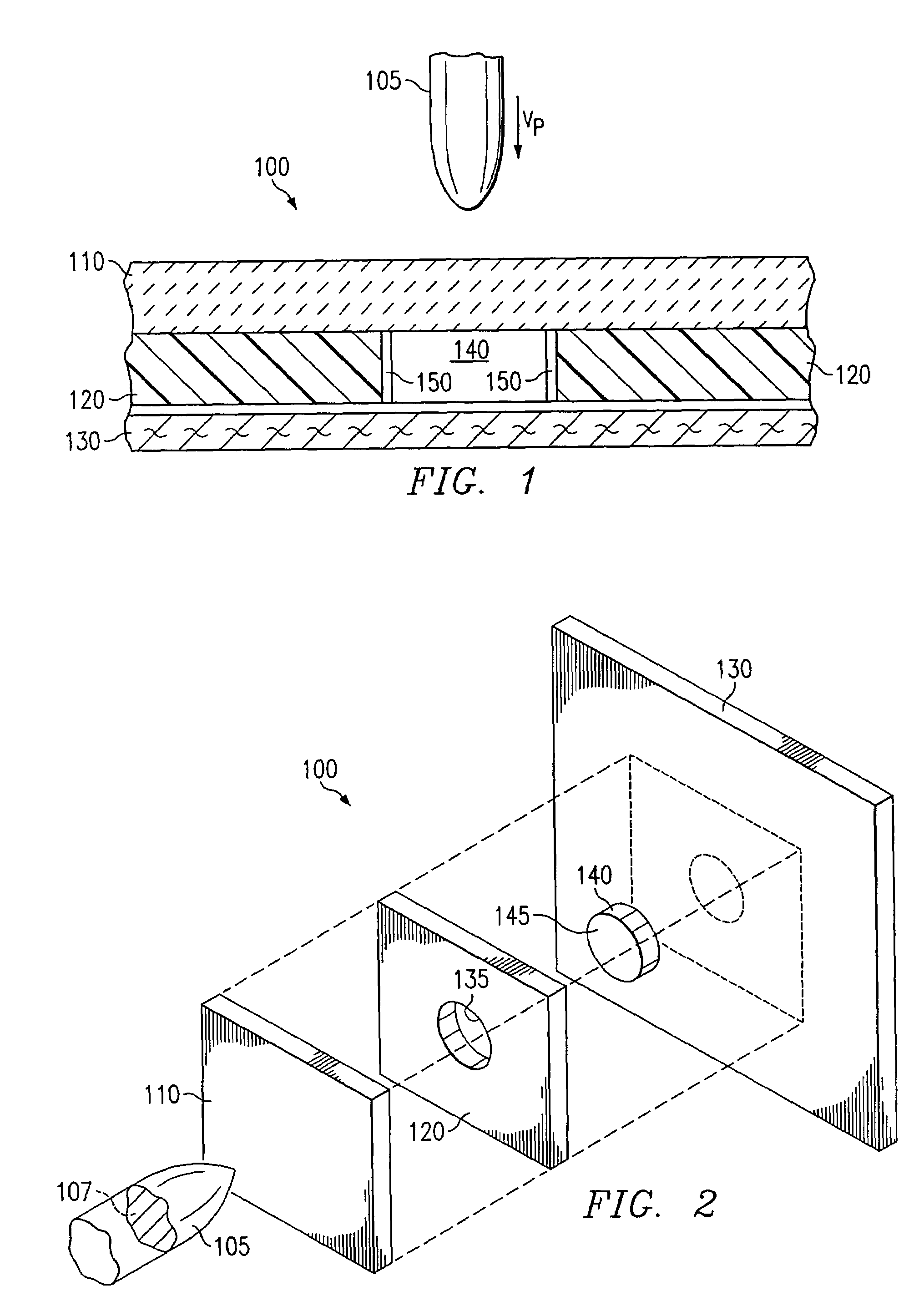
[0024]Generally, the ballistic performance of protective materials, especially fabric, increases with the presented area of the projectile. FIG. 1 illustrates a side, cut-away view of the momentum trap ballistic armor system 100 of the present invention. In this case, a ballistic projectile 105 is traveling at a projectile velocity (Vp) toward the system 100, comprising an accelerating layer 110, a plug layer 120, and optionally, an energy absorbing layer 130. The energy absorbing layer 130 may form an integral part of the system 100, or exist as a separate element, such as a shirt worn under an armored vest.

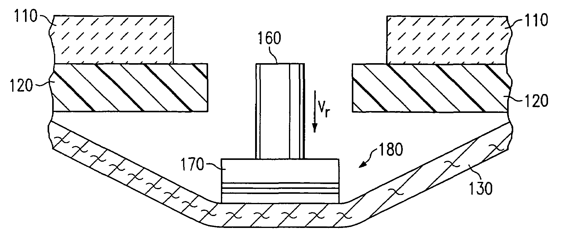
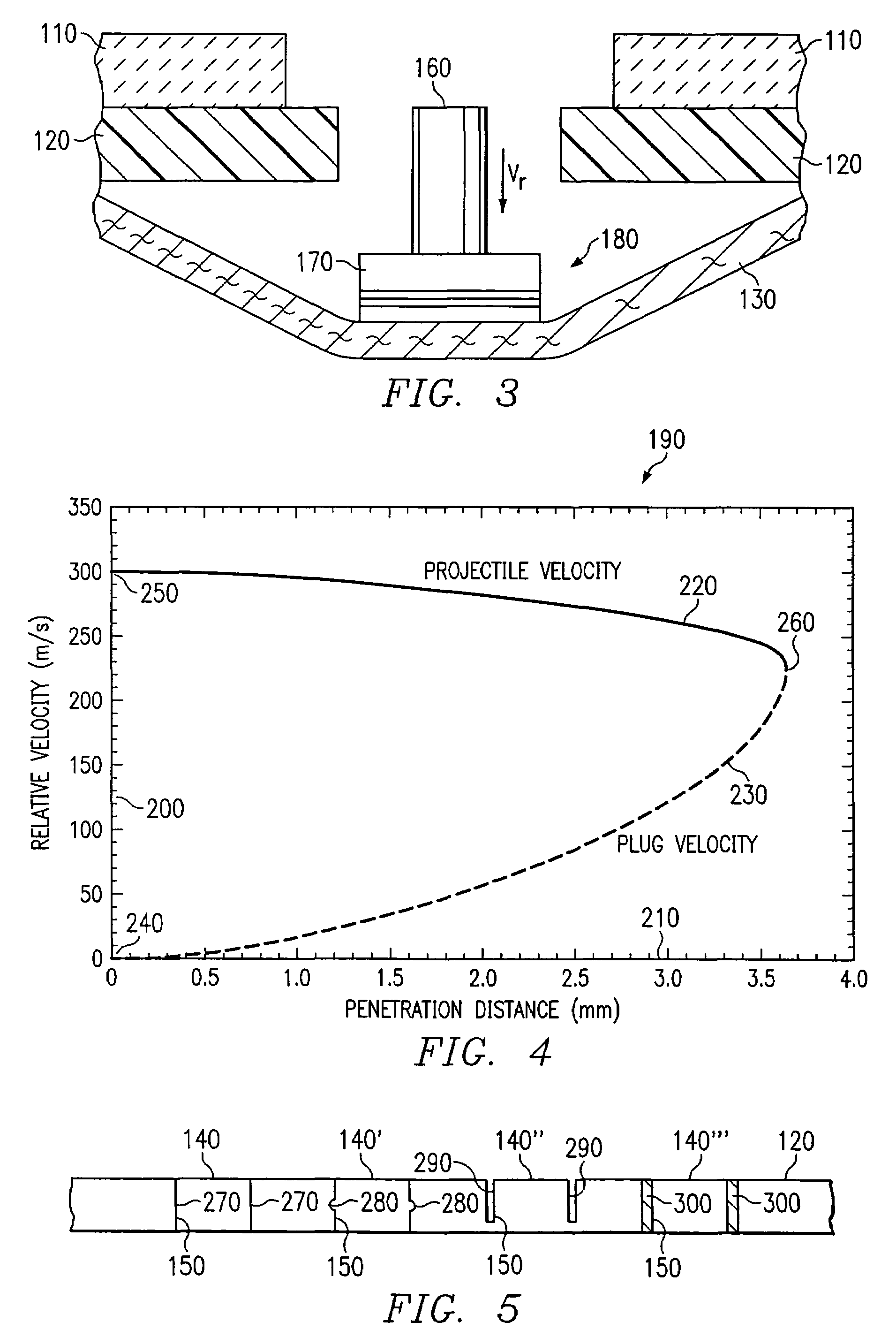
[0025]FIG. 2 illustrates the elements of the momentum trap ballistic armor system 100 of the present invention. FIG. 3 illustrates the operation of the armor system to deform and reduce the velocity of the projectile 105. The mechanics associated with the armor system 100 can be thought of as a competition between the projectile 105 penetrating the plug 140 as it decelerates, wh...


PUM


Abstract

A momentum trap ballistic armor comprises an accelerating layer, a plug layer adjacent to the accelerating layer, and an energy absorbing layer. The plug layer includes an opening and at least one plug maintained within the opening. When a projectile impacts the accelerating layer, the plug is accelerated to the velocity of the projectile before the projectile perforates the plug, forming a projectile-plug combination. The energy absorbing layer is used to capture the projectile-plug combination. The accelerating layer is typically ceramic, the plug layer is typically metal, and the energy absorbing layer is typically ballistic cloth material.

Description

RELATED APPLICATIONS[0001]This application is a Divisional of U.S. patent application Ser. No. 09 / 887,298, now U.S. Pat. No. 6,718,861, entitled “Momentum Trap Ballistic Armor System,” filed by Charles E. Anderson Jr. et al. on Jun. 22, 2001.GOVERNMENTAL RIGHTS[0002]The U.S. Government has a paid-up license in this invention and the right in certain circumstances to require the patent owner to license others on reasonable terms as provided for by the terms of Contract No. DAAK60-97-C-9228 for the U.S. Army Soldiers System Command.TECHNICAL FIELD OF THE INVENTION[0003]This invention relates generally to the field of apparatus and systems for shielding personnel and other objects from hostile activity, including objects or projectiles fired from a gun or resulting from explosions. More particularly, this invention relates to an armoring system which operates to trap ballistic projectiles using a combination of layered components, including plugs.BACKGROUND OF THE INVENTION[0004]Many d...

Claims


Application Information

Patent Timeline
IPC IPC(8): F41H5/04F41H5/08
CPCF41H5/04
Inventor ANDERSON, JR., CHARLES E.ORPHAL, DENNIS L.JOHNSON, GORDON R.
Owner SOUTHWEST RES INST
Why Eureka
Try Eureka