Powered dispenser for interconnected strip bandages

a technology of interconnected strips and dispensers, which is applied in the direction of bandages, instruments, de-stacking articles, etc., can solve the problems of mechanical dispersion, affecting the operation of the bandage, and the feeding structure malfunction, and achieves the effect of simple and economic manufactur

Inactive Publication Date: 2006-07-18
ROSS NADINE
View PDF18 Cites 26 Cited by
  • Summary
  • Abstract
  • Description
  • Claims
  • Application Information

AI Technical Summary

Benefits of technology

[0013]A still further object is to provide such a dispenser that is of new and novel design, of rugged and durable nature, of simple and economic manufacture and one that is otherwise well suited to the uses and purposes for which it is intended.

Problems solved by technology

A problem arises in mechanically dispersing strip bandages from a rolled supply source that can be troublesome, but does not appear to have been addressed by the prior art.
The problem manifests itself when individual bandages in the supply roll are dispersed in a mechanism that moves the supply roll by moving and simultaneously stripping the cover strips from each side of the strip bandage roll as the cover strip on the inner side of the supply roll will have less length to become more tight and the cover on the outer side of the supply roll will have more length to become more loose.
This action, if not accommodated, disrupts synchronization of take up type waste rolls if used as feeding mechanism and can cause malfunction of the feeding structure, disrupt its operability and require substantial maintenance activity.

Method used


Image

  • Powered dispenser for interconnected strip bandages
  • Powered dispenser for interconnected strip bandages
  • Powered dispenser for interconnected strip bandages

Examples


Embodiment Construction

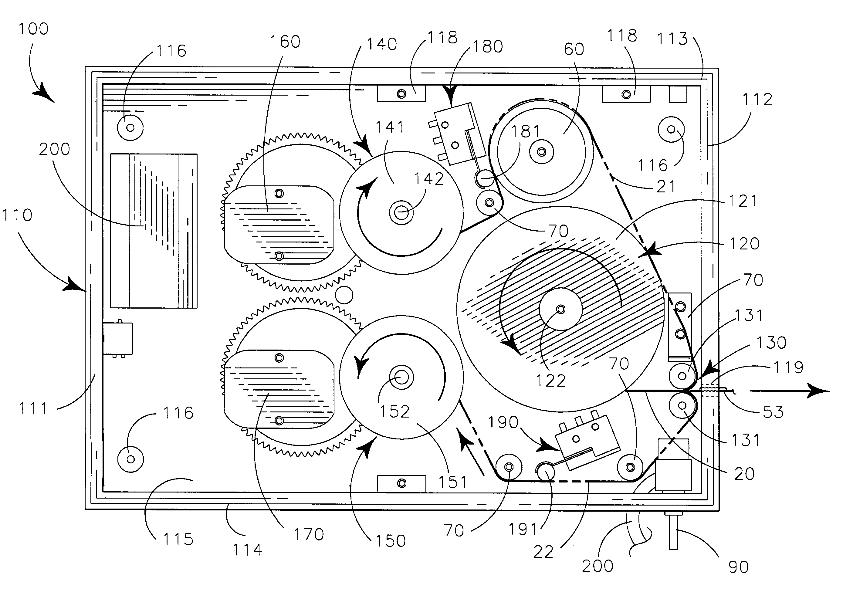
[0020]My dispenser apparatus 100 provides casement 110 carrying bandage supply 50 on bandage support device 120 to pass the bandage supply 50 through cover strip separator device 130 to separate cover strips of the bandage supply 50 and pass them along first waste path 21 and second waste path 22 to first cover strip take-up device 140 and second cover strip take-up device 150, respectively. The take-up devices 140,150 are powered by first motor 160 and second motor 170 respectively. Each waste path 21, 22 has associated first tension sensor 180 and second tension sensor 190 respectively to control motion of first motor 160 and second motor 170 respectively.

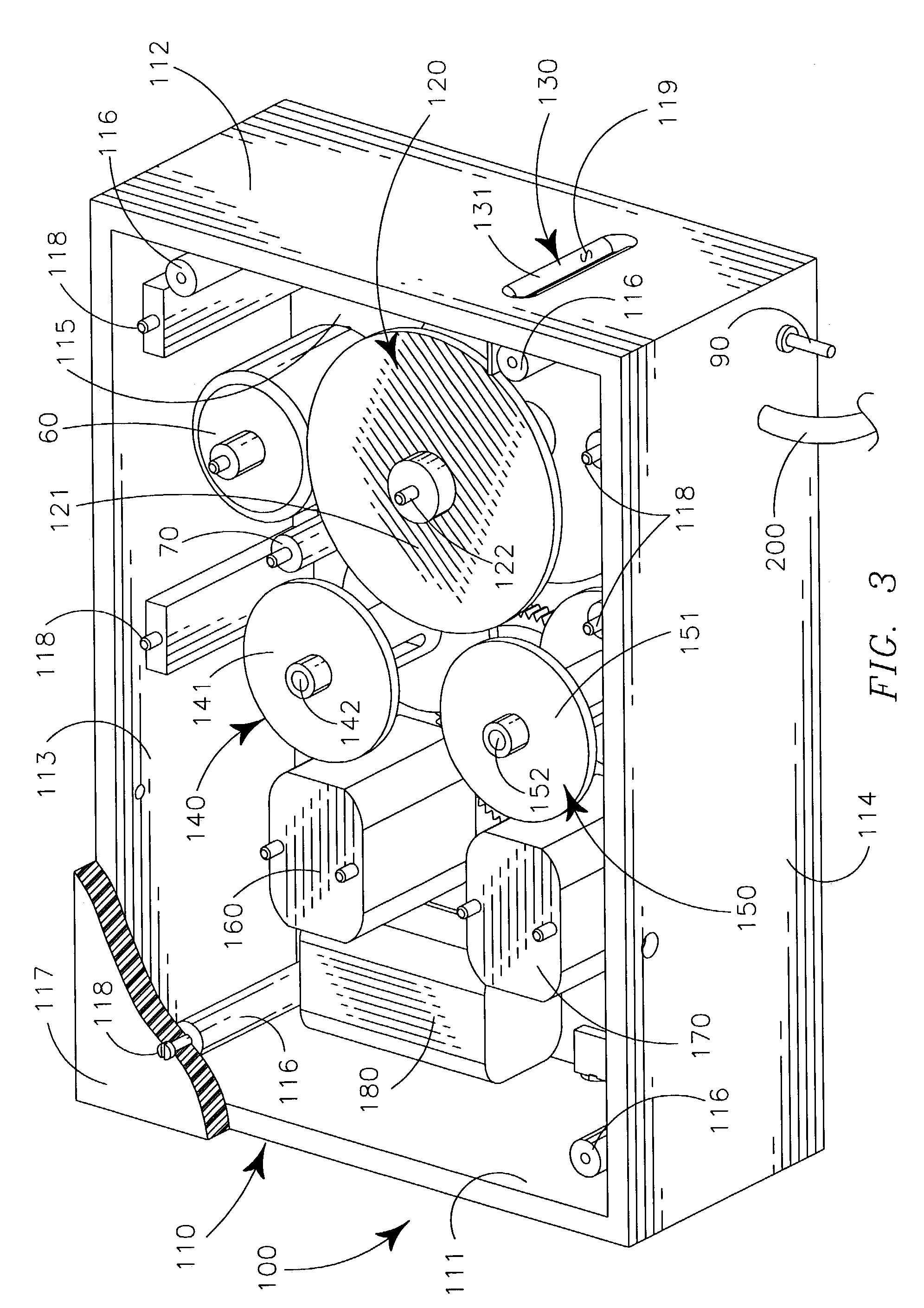
[0021]FIG. 3 is an isometric view dispenser apparatus 100 in accordance with one specific embodiment of the invention. The dispenser apparatus 100 is generally configured to disperse bandages (not shown) as described in greater detail hereinafter. The dispenser apparatus 100 includes casement 110, substantially in the form of a b...


PUM

PropertyMeasurementUnit
tensive forceaaaaaaaaaa
tensionaaaaaaaaaa
dispersionaaaaaaaaaa

Abstract

A dispenser for individual strip bandages from a rolled elongate bandage supply having the individual strip bandages releasably interconnected between a pair of cover strips defining chambers about each strip bandage. The dispenser provides a feed spindle carrying the bandage supply that is moved to a cover strip separator adjacent to a delivery slot in a casement. The cover strips are removed from a given strip bandage in the separator and pass along waste courses to motor powered take-up devices which move the bandage supply and disperse the given strip bandage through the delivery slot. At least one cover strip waste course has a tension sensor to sense tension in the associated cover strip to control the take-up device moving the associated cover strip to maintain synchronization of the motion of the pair of cover strips on the take-up devices moving them.

Description

II. BACKGROUND OF INVENTIONII.A Related Applications[0001]There are no applications related hereto heretofore filed in this or any foreign country.II.B Field of Invention[0002]My invention relates generally to article dispersing and more particularly to a powered dispenser for a rolled elongate strip of adhesive bandages carried between opposed cover strips.II.C Background and Description of Prior Art[0003]Since the advent of bandages that combined an absorbent material with an adhesive element this type of bandage has become increasing popular and in the present day has become fairly sophisticated and somewhat standardized in configuration. This type of bandage in its earlier developmental stages was individually packaged or containerized in some type of casement that maintained sterility until the time of use as epitomized by the Band-Aid® of Johnson & Johnson Pharmaceutical Company (hereinafter generically “strip bandage”) widely used in individual packaging, especially by indivi...

Claims


Application Information

Patent Timeline
Patent Type & Authority Patents(United States)
IPC IPC(8): B65H5/00G07F11/68B65H18/08B65H5/28B65H18/00A61F15/00
CPCA61F15/002B65H5/28G07F11/68B65H2701/194B65H2301/41912
Inventor ROSS, NADINE
Owner ROSS NADINE
Why Eureka
Try Eureka