Fluid flow machine with integrated fluid circulation system

a fluid circulation system and fluid flow technology, applied in the direction of machines/engines, liquid fuel engines, pumps and blowers, etc., can solve the problems of affecting the thermodynamic process of the overall system surrounding, affecting the thermodynamic process of the overall system, and requiring additional energy input and mass flow loss

Inactive Publication Date: 2006-07-18
ROLLS ROYCE DEUT LTD & CO KG
View PDF16 Cites 31 Cited by
  • Summary
  • Abstract
  • Description
  • Claims
  • Application Information

AI Technical Summary

Benefits of technology

[0024]It can further be advantageous if the line for the collection of the fluid quantities removed from individual blades of the fluid-flow machine is provided with a discharge chamber into which individual lines issue or from which the line or several lines go out, with this discharge chamber being preferably situated on the periphery of the main flow path. In a similar manner, a supply chamber may be provided. Both the discharge and the supply chamber serve the steadiness of the fluid flow and the associated pressure compensation, as necessary.

Problems solved by technology

The aerodynamic loadability of components of a fluid-flow machine, for example fans, compressors, pumps and blowers, is limited by the growth and the separation of profile boundary layers on the blade surfaces and side-wall boundary layers forming on the hub and the casing.
Both an additional energy input and a loss in mass flow will impair the thermodynamic process of the overall system surrounding the fluid-flow machine.
Some concepts make use of a recirculation from blade row to blade row, but with each blade row being limited to either the removal or the supply of fluid.

Method used


Image

  • Fluid flow machine with integrated fluid circulation system
  • Fluid flow machine with integrated fluid circulation system
  • Fluid flow machine with integrated fluid circulation system

Examples


Embodiment Construction

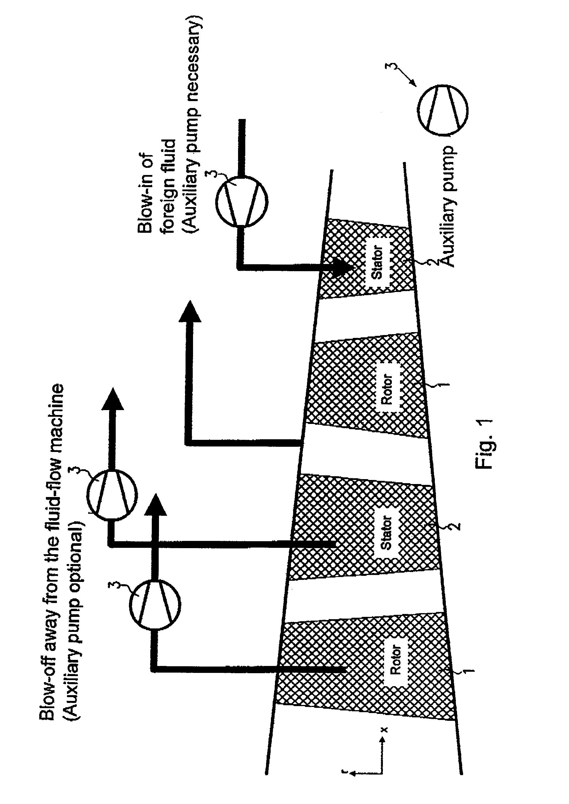
[0034]FIG. 1 shows schematically the solutions known from the state of the art for fluid removal or fluid supply, respectively. As shown, fluid is blown off from a rotor or a stator (rotor blade or stator blade) and away from the fluid-flow machine. An auxiliary pump 3 can be used for this purpose. It is further known to supply fluid from an external source, for example an auxiliary pump, to a rotor or a stator.

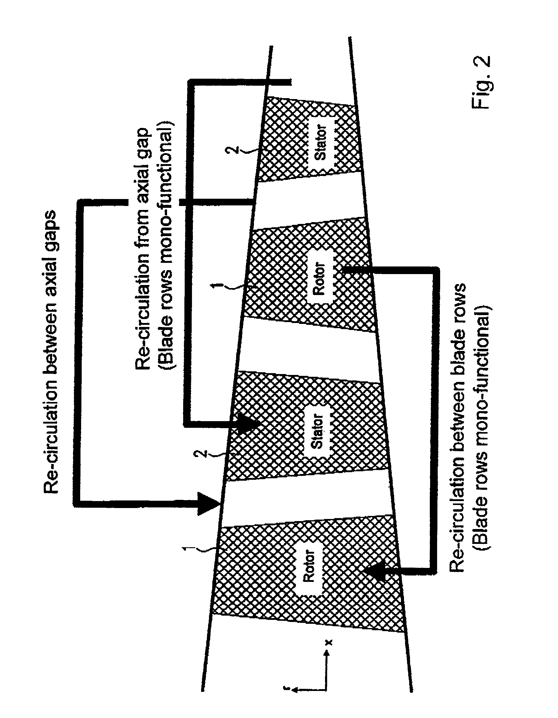
[0035]FIG. 2 shows further solutions according to the state of the art. These include re-circulation between axial gaps, re-circulation between axial gap and blade row (rotor or stator) and re-circulation between blade rows (rotor or stator).

[0036]FIG. 3 illustrates the scope of application of the present invention by way of some possible configurations of the main flow path of the fluid-flow machine in accordance with the present invention, with integrated fluid circulation system.

[0037]FIG. 4 shows definitions of the term “throat-limiting surfaces” as used in the present in...


PUM


Abstract

A fluid-flow machine includes at least one rotor and a free number of stators flown by a fluid, with at least one blade thereof positioned on throat-confining surfaces provided with both a device for fluid removal from the flow path and a device for fluid supply into the flow path (bi-functionality). The machine includes at least one line associated with the device for fluid removal for returning the removed fluid to an upstream position in the flow path and at least one further line associated with the device for fluid supply for supplying the fluid from a further downstream position in the flow path.

Description

[0001]This application claims priority to German Patent Application DE10233032.8 filed Jul. 20, 2002, the entirety of which is incorporated by reference herein.[0002]This invention relates to a fluid-flow machine with an integrated fluid circulation system.BACKGROUND OF THE INVENTION[0003]The aerodynamic loadability of components of a fluid-flow machine, for example fans, compressors, pumps and blowers, is limited by the growth and the separation of profile boundary layers on the blade surfaces and side-wall boundary layers forming on the hub and the casing.[0004]For fans, compressors, pumps and blowers, the state of the art only restrictively provides concepts for the internal guidance of a fluid drawn off at particularly favorable locations and the re-introduction of this fluid into the main flow path at again particularly favorable locations.[0005]The state of the art mostly shows solutions in which a drawn-off fluid quantity is permanently removed from the main flow path of the ...

Claims


Application Information

Patent Timeline
Patent Type & Authority Patents(United States)
IPC IPC(8): F01D25/24F04D27/02F04D29/68
CPCF04D27/0215F04D27/009F04D29/681F04D27/0207F04D29/324F04D29/542F04D29/682F04D29/684
Inventor GUEMMER, VOLKER
Owner ROLLS ROYCE DEUT LTD & CO KG
Why Eureka
Try Eureka