Light source apparatus for endoscope

Inactive Publication Date: 2006-07-18
HOYA CORP
View PDF12 Cites 12 Cited by
  • Summary
  • Abstract
  • Description
  • Claims
  • Application Information

AI Technical Summary

Benefits of technology

[0008]The present invention eliminates the drawbacks of the prior art mentioned above by providing a light

Problems solved by technology

It is not desirable that the endoscope stays in a body cavity of a patient during the replacement.
However, if the auxiliary light source is made of a high intensity LED, the amount of light emitted therefrom is smaller than that of the main light source and, hence

Method used


Image

  • Light source apparatus for endoscope
  • Light source apparatus for endoscope
  • Light source apparatus for endoscope

Examples


first embodiment

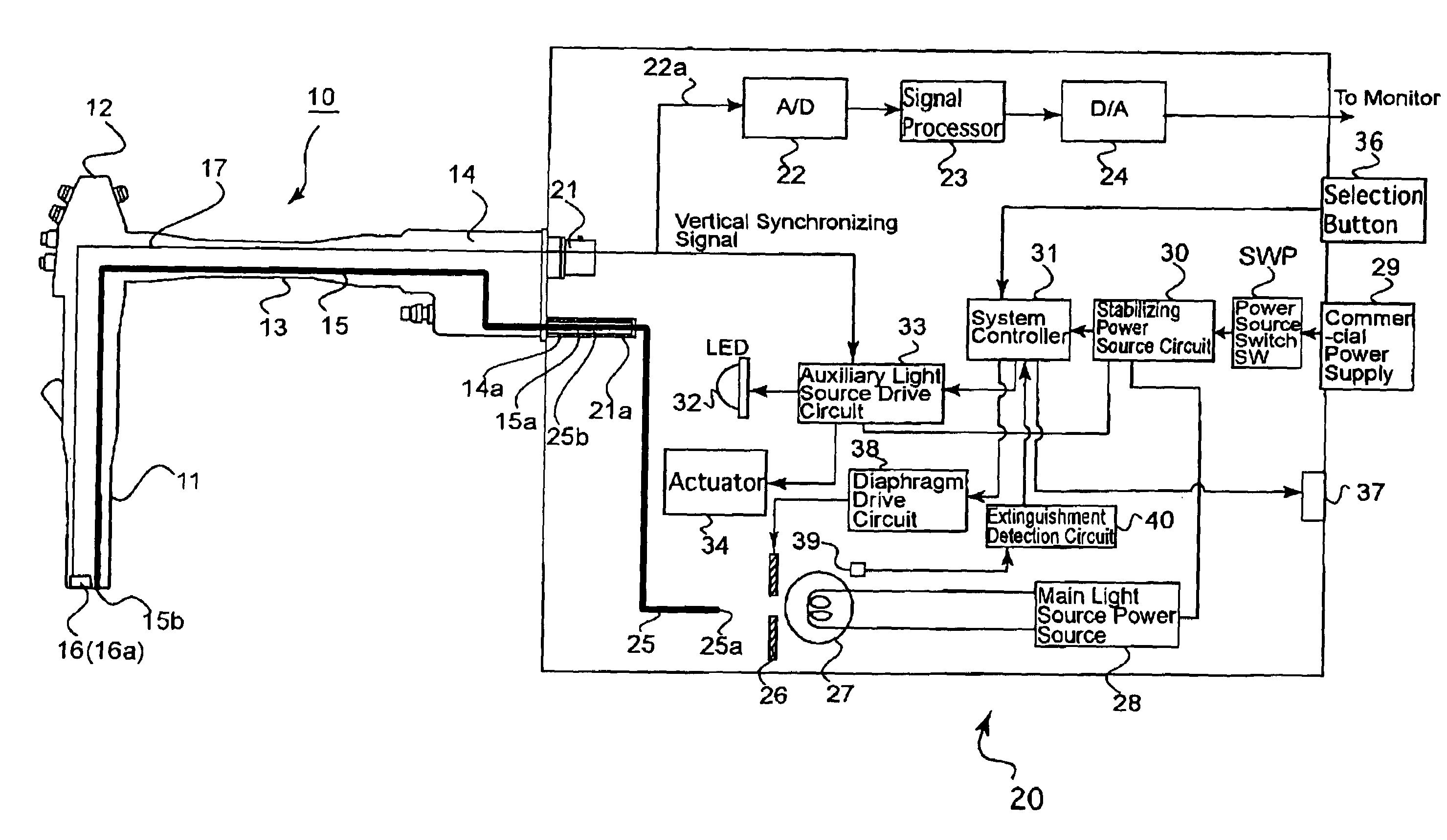
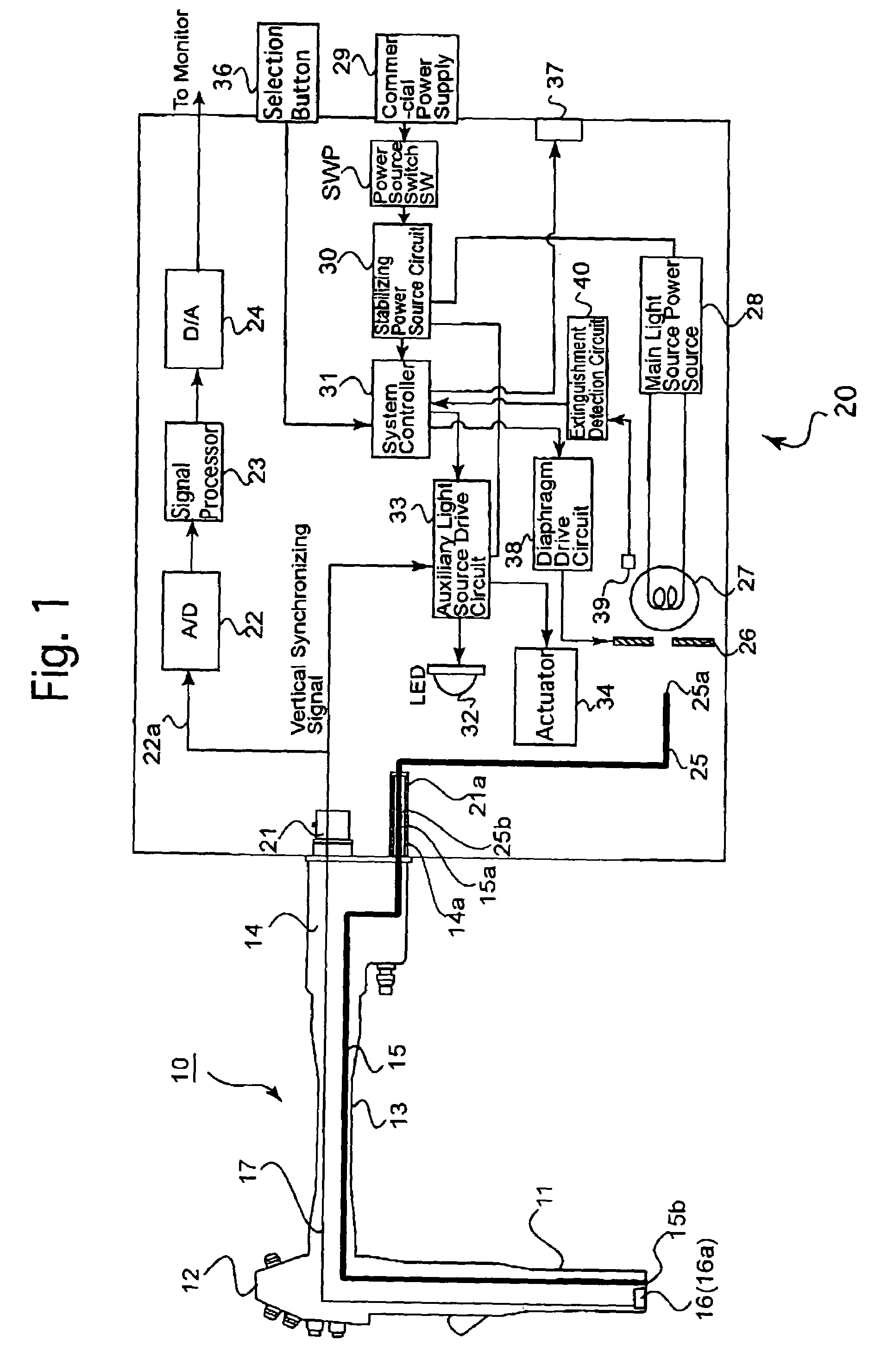
[0025]FIG. 1 shows main components of a light source apparatus applied to an electronic endoscope system, according to the present invention.

[0026]The electronic endoscope 10 is comprised of a flexible insertion portion 11, an operating portion 12 provided at an external end of the insertion portion 11, and a universal tube 13 connected to the operating portion 12. The insertion portion 11 is provided on its front end with a built-in electronic camera 16 including an image pickup lens and an image pickup device (CCD), etc. The electronic camera 16 can pickup an external object through a view window (object window) formed at the front end face of the insertion portion 11. The insertion portion 11 is provided on its front end face with an emission end face 15b of a light guide (a bundle of optical fibers) 15 as an illumination light guiding means and an outlet port of forceps channel (not shown), etc. The operating portion 12 is provided with operation buttons for controlling a motion...

second embodiment

[0054]The operation to turn the auxiliary light source in the second embodiment will be discussed below with reference to a flow chart shown in FIG. 9. The operation in this flow chart is performed as a sub-routine of S23 in FIG. 6.

[0055]In this flow chart, whether or not the light guide detection sensor 41 is ON (whether or not the light guide is connected) is checked (S61). If the light guide detection sensor is not turned ON, (no light guide is mounted), the auxiliary light source 32 is turned OFF and the control is returned (S61; N, S63, RETURN). If the light guide detection sensor 41 is ON (the light guide is mounted), whether or not the electric connector detection sensor 42 is ON (the electronic endoscope is mounted) is checked if the electric connector detection sensor 42 is ON (the electronic endoscope is mounted), the auxiliary light source drive circuit 33 is driven at the pulse-current emission mode to activate the auxiliary light source 32 at a pulse-current, and the co...


PUM


Abstract

A light source apparatus for an endoscope including a main light source; a light guide member whose incident end face is opposed to the main light source and which guides light incident thereon to an emission end face thereof; an auxiliary light source which is activated to emit light when no light is emitted from the main light source and which is supported to move between a stand-by position in which the auxiliary light source is located out of a main light path between the main light source and the incident end face and an operative position in which the auxiliary light source is located in the main light path and is opposed to the incident end face when the main light source is inoperative; and an auxiliary light source emission control device for driving the auxiliary light source at a continuous emission mode to emit light of a predetermined intensity or at an intermittent emission mode to emit light of an intensity higher than the predetermined intensity.

Description

BACKGROUND OF THE INVENTION[0001]1. Field of the Invention[0002]The present invention relates to a light source apparatus for an electronic scope or a fiber scope.[0003]2. Description of the Related Art[0004]A high intensity lamp, such as a halogen lamp, a mercury vapor lamp or a metal halide lamp is used as a light source of a light source apparatus for an endoscope. If the light source goes off due to expiration of the service life thereof or trouble during examination or an operation using an endoscope, it is necessary to replace the light source or the light source apparatus with a new one. It is not desirable that the endoscope stays in a body cavity of a patient during the replacement.[0005]To solve this problem, it has been proposed to provide a separate auxiliary light source in addition to a main light source of a high intensity lamp, wherein if the main light source goes off, the auxiliary light source is used to illuminate a body cavity of a patient, so that an insertion ...

Claims


Application Information

Patent Timeline
IPC IPC(8): A61B1/06H01L33/00A61B1/07G02B23/24F21S2/00F21V8/00F21W131/20F21Y101/00H04N5/238
CPCA61B1/0684A61B1/0669
Inventor OTA, NORIKO
Owner HOYA CORP
Why Eureka
Try Eureka