Syringe for sequential delivery of different fluids

a technology of fluids and syringes, applied in the field of sequential administration of fluids, can solve the problems of difficult and expensive manufacturing steps, awkward two-needle system, increased risk of inadvertent needlesticks for medical personnel,

Inactive Publication Date: 2006-07-18
JOHNSON DR CHRIS
View PDF14 Cites 68 Cited by
  • Summary
  • Abstract
  • Description
  • Claims
  • Application Information

AI Technical Summary

Benefits of technology

[0012]The length of the valve is slightly less than the thickness of the floating piston such that the piston is normally slightly compressed thereby maintaining the sealing disk in sealing engagement with the upper end of the passageway. As the plunger of the syringe is moved axially through the barrel thereof toward the needle of the syringe, the fluid in the portion of the barrel extending above the floating piston forces the floating piston toward the needle of the syringe thereby forcing the fluid in the lower portion of...

Problems solved by technology

The two needle system is not only awkward but also increases the risk that medical personnel will suffer inadvertent needlesticks.
As will be appreciated by those skilled in the art, forming a porthole in a hollow needle of the type utilized in medical syringes involves difficult and expensive manufactu...

Method used


Image

  • Syringe for sequential delivery of different fluids
  • Syringe for sequential delivery of different fluids
  • Syringe for sequential delivery of different fluids

Examples


first embodiment

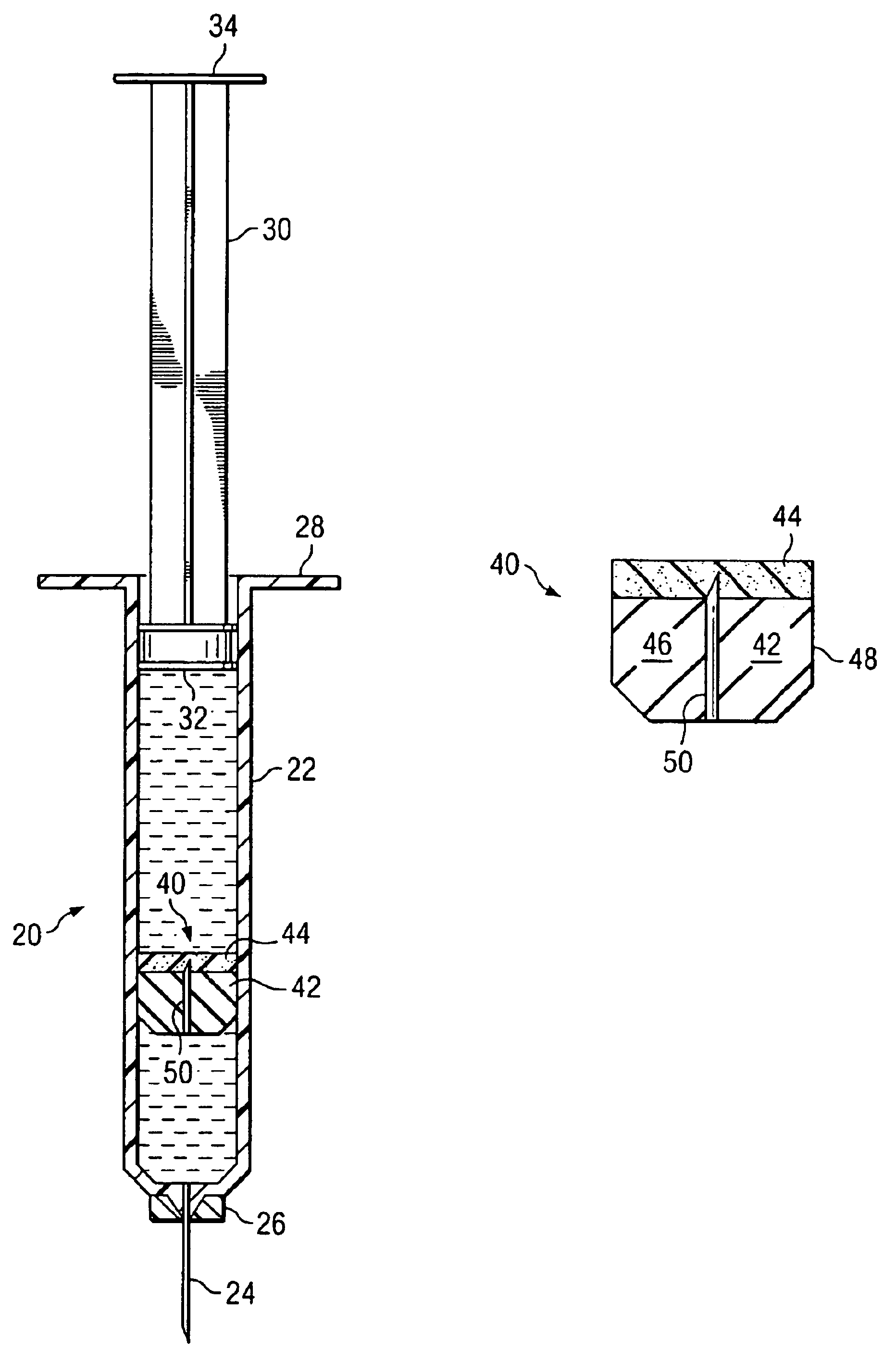
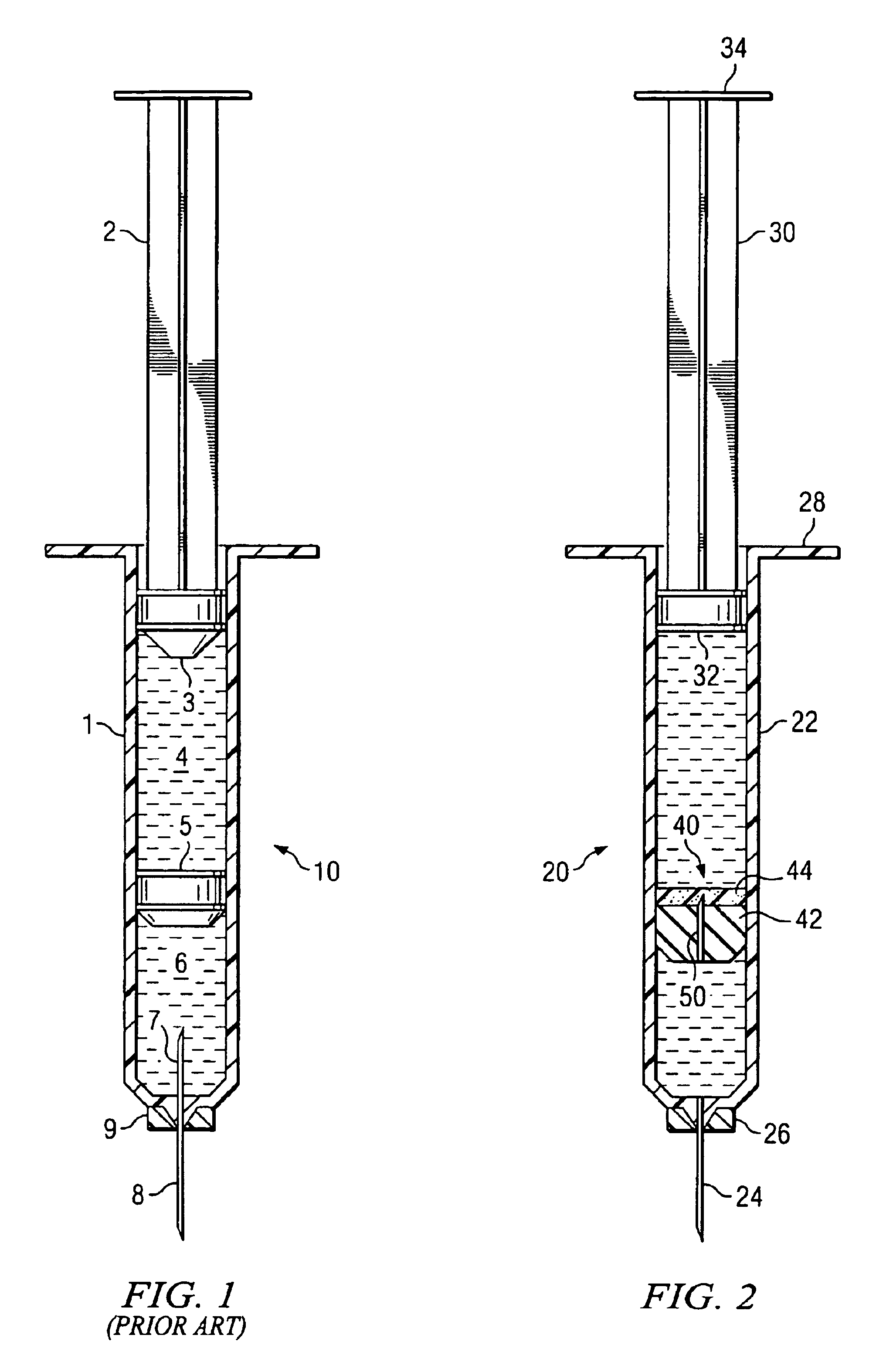
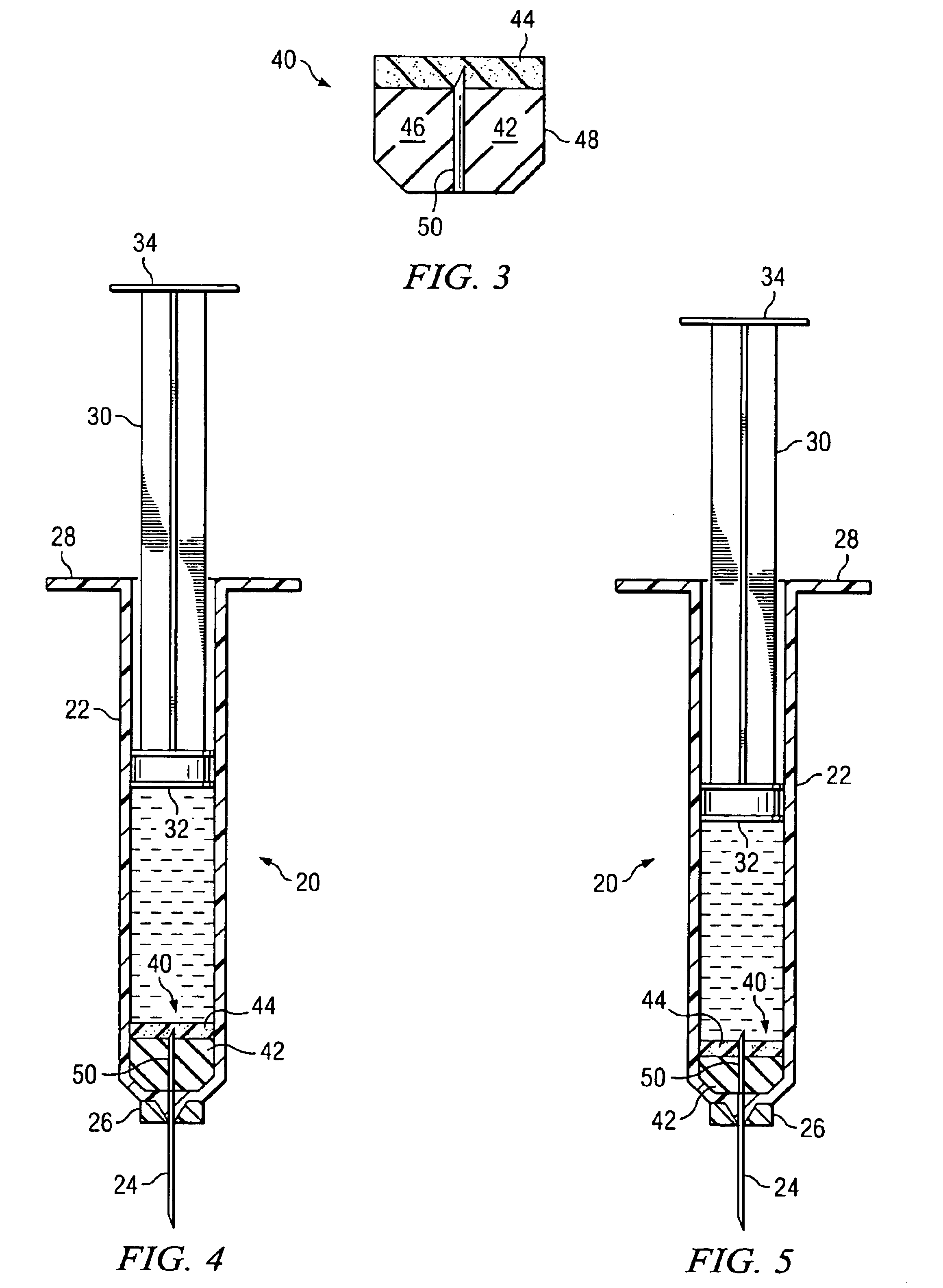
[0024]Referring now to the Drawings, and particularly to FIG. 2 thereof, there is shown a syringe 20 comprising the present invention. In many respects the syringe 20 is conventional in construction and operation. Thus, the syringe 20 includes a barrel 22 which receives fluid to be administered. A hollow needle 24 is secured to one end of the barrel 22 by a hub 26 and is coupled in fluid communication with the interior of the barrel 22. The end of the barrel 22 remote from the needle 24 may be provided with a radially extending flange 28 which is typically engaged by the fingers of an individual operating the syringe 20.

[0025]The syringe 20 further includes a plunger 30 adapted for axial movement within the barrel 22. The plunger 30 extends to a piston 32 which forms a fluid tight seal with the interior surface of the barrel 22. The end of the plunger 30 remote from the piston 32 may be provided with a plate 34 which is typically engaged by the thumb of an individual operating the s...

second embodiment

[0033]Referring to FIGS. 7 through 10, inclusive, there is shown a syringe 60 comprising the present invention. In many respects the syringe 60 is conventional in construction and operation. Thus, the syringe 60 includes a barrel 62 which receives fluid to be administered. A hollow needle 64 is secured to one end of the barrel 62 by a hub 66 and is coupled in fluid communication with the interior of the barrel 62. The end of the barrel 62 remote from the needle 64 may be provided with a radially extending flange 68 which is typically engaged by the fingers of an individual operating the syringe 60.

[0034]The syringe 60 further includes a plunger 70 adapted for axial movement within the barrel 62. The plunger 70 extends to a piston 72 which forms a fluid tight seal with the interior surface of the barrel 62. The end of the plunger 70 remote from the piston 72 may be provided with a plate 74 which is typically engaged by the thumb of an individual operating the syringe 60.

[0035]The syr...


PUM


Abstract

A syringe for sequentially administering different fluids includes a floating piston which separates the syringe into a first portion for receiving a first fluid to be administered and a second portion for receiving a second fluid to be administered. The floating piston includes a fluid tight seal which initially separates the first and second portions of the syringe and apparatus for connecting the second portion of the syringe to the syringe needle after the first fluid has been discharged from the syringe.

Description

CROSS-REFERENCE TO RELATED APPLICATIONS[0001]This application is a continuation-in-part application of application Ser. No. 10 / 231,827 filed Aug. 30, 2002 abandoned.TECHNICAL FIELD[0002]This invention relates generally to the sequential administration of different fluids, for example, the administration of a medication followed immediately by the administration of a normal saline solution, and more particularly to an improved syringe design which assures complete delivery of the first fluid followed immediately by complete delivery of the second fluid.BACKGROUND AND SUMMARY OF THE INVENTION[0003]Various medical procedures require the sequential administration of different fluids. For example, administration of the cardiac drug known as Adenosine must be followed immediately by the administration of a normal saline solution in order to get the drug into circulation rapidly. Heretofore the sequential administration of different fluids has been accomplished utilizing two syringes, one ...

Claims


Application Information

Patent Timeline
IPC IPC(8): A61M5/00A61M5/28
CPCA61M5/284A61M5/286A61M2005/1787
Inventor GREENFIELD, CHRISTIAN JOHN
Owner JOHNSON DR CHRIS
Why Eureka
Try Eureka