Ferrite core

Inactive Publication Date: 2006-07-18
HOFFMAN THOMAS K +1
View PDF4 Cites 11 Cited by
  • Summary
  • Abstract
  • Description
  • Claims
  • Application Information

AI Technical Summary

Benefits of technology

[0011]In view of the foregoing disadvantages inherent in the known types of ferrite cores now present in the prior art, the present invention provides a new ferrite core construction wherein the same can be utilized for minimizing the circuit board footprint of a core-based component while also minimizing the total harmonic distortion exhibited by the component.

Problems solved by technology

However, factors have combined to make these designs less than optimal for use in applications where circuit board space is at a premium, where the least amount of total harmonic distortion is desirable, and where interference between adjacent components should be minimized.
Increasing the number of turns in the components results in a number of detrimental effects, such as increased leakage inductance, increased distributive capacitance, increased capacitance between the primary and secondary windings of transformer components, and a general decrease in the bandwidth capacity of the components.

Method used


Image

  • Ferrite core
  • Ferrite core
  • Ferrite core

Examples


Embodiment Construction

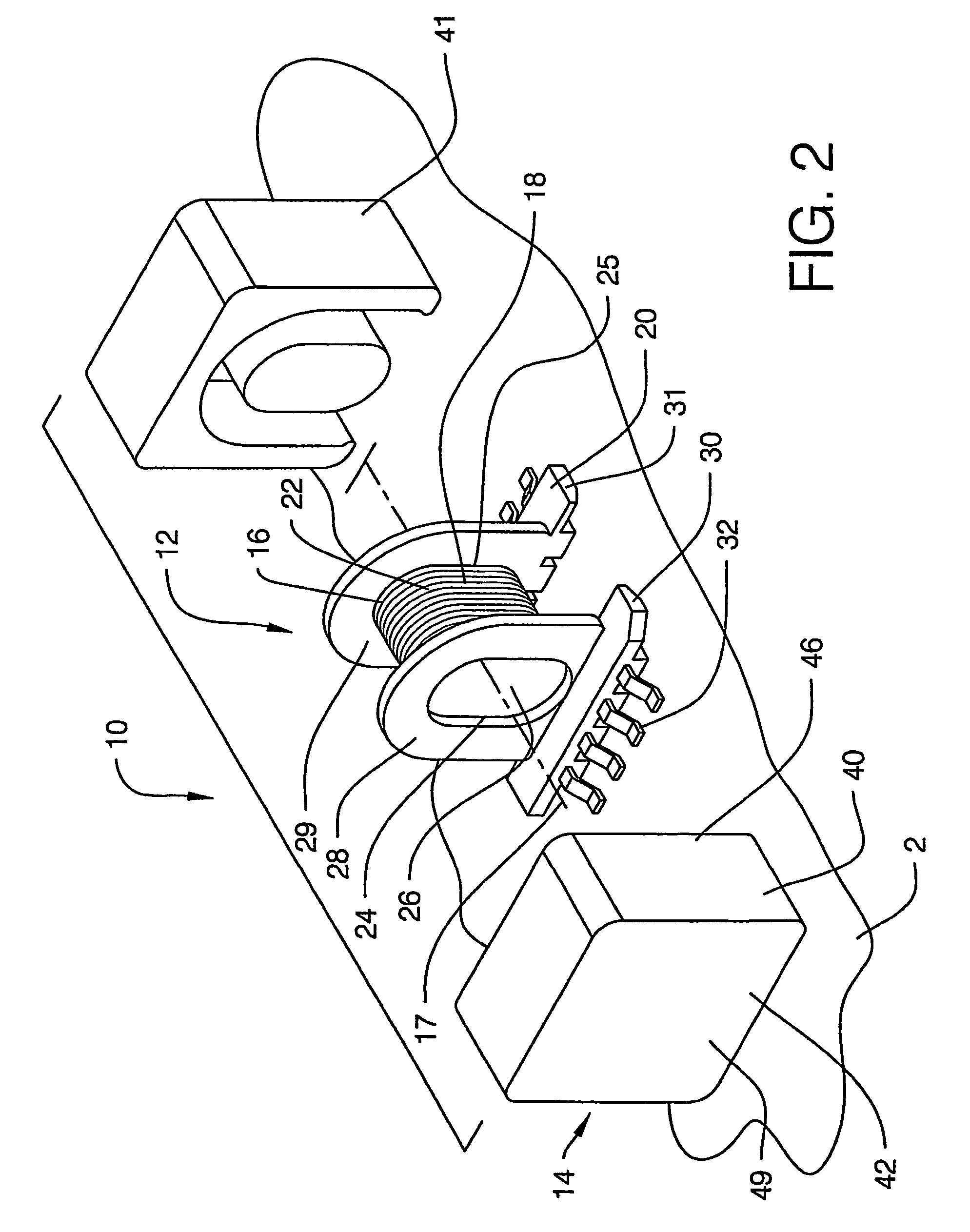
[0026]With reference now to the drawings, and in particular to FIGS. 2 through 8 thereof, a new ferrite core embodying the principles and concepts of the present invention is illustrated.

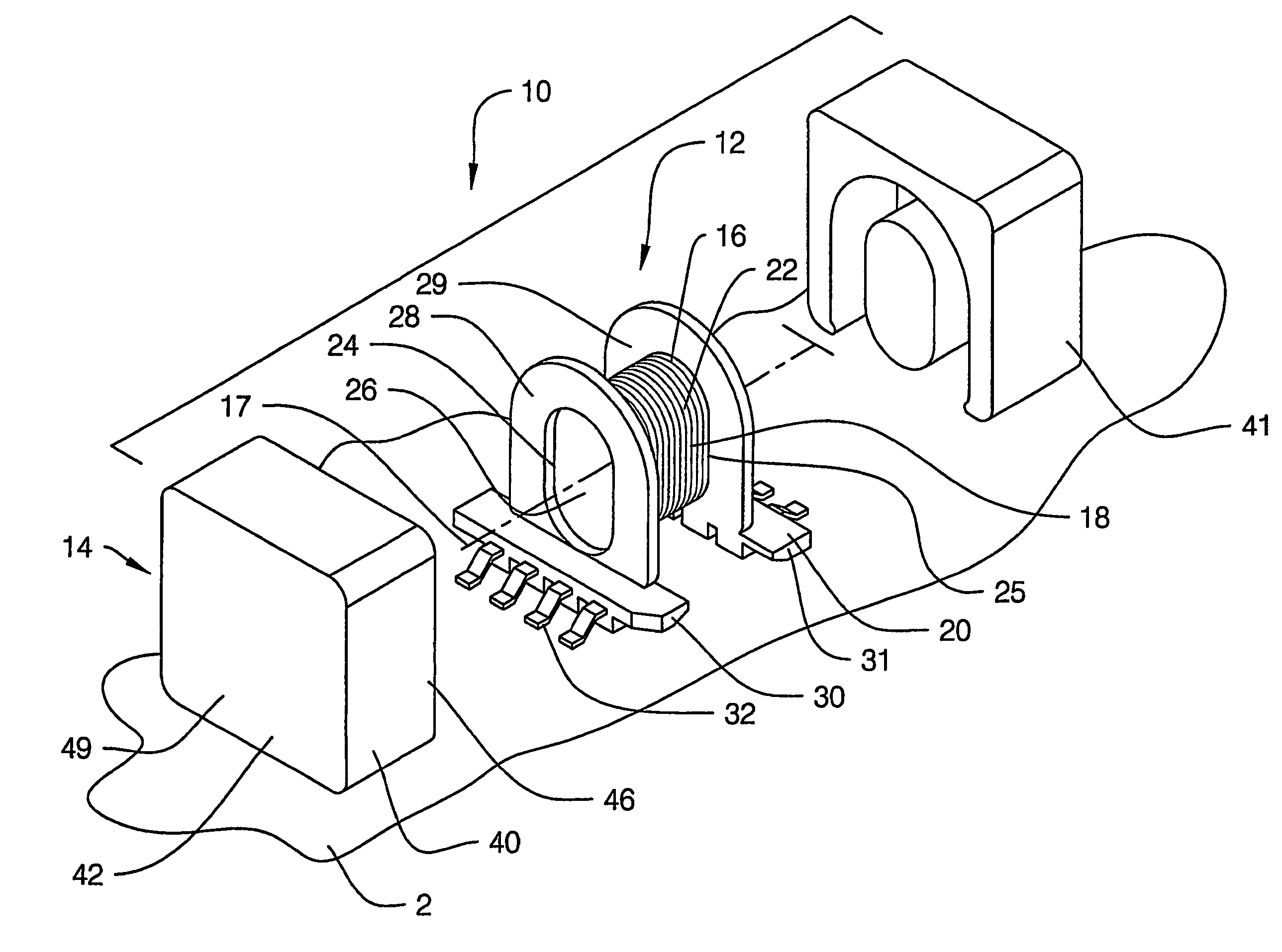
[0027]The ferrite core of the invention is highly suitable for use in a component 10 employing a coiled conductor 16 such as, for example, a transformer or an inductor. The core of the invention is especially suitable in applications where it is desirable to have low harmonic distortion created by the component, such as where the component is primarily employed for signal handling, although the core may also be employed in components employed in power supply applications.

[0028]The ferrite core of the invention is suitably employed in a component 10 that includes a coil assembly 12 and a core assembly 14. The coil assembly 12 may comprise a bobbin 18, a coiled conductor 16 mounted on the bobbin, and a base structure 20 for mounting the bobbin on a circuit board. Components of this type are typically ...


PUM


Abstract

A core for minimizing the footprint of a core-based components while also minimizing the total harmonic distortion exhibited by the component. The core (40) includes a back wall portion (42), a central wall portion (44), and an outside wall portion (46). The back wall portion has a front (48) and a back (49), with a lower end (51), an upper end (52), and a pair of sides (54,55) extending between the lower and upper ends. The central leg portion protrudes from the front of the back wall portion, and the central leg portion is substantially centrally located on the front of the back wall portion. The outside wall portion protrudes from the front of the back wall portion. The central leg portion is elongated along a first axis extending between the upper and lower ends of the back wall portion. Optionally, the central leg portion is spaced from the lower edge of the back wall portion.

Description

BACKGROUND OF THE INVENTION[0001]1. Field of the Invention[0002]The present invention relates to ferrite cores and more particularly pertains to a new ferrite core for minimizing the circuit board footprint of a core-based component while also minimizing the total harmonic distortion exhibited by the component.[0003]2. Description of the Prior Art[0004]The use of ferrite cores is known in the prior art. The ferrite cores are situated in close proximity to coiled conductors to facilitate the flow of magnetic flux between the coils of a coiled conductor.[0005]Some of the most popular prior art designs for ferrite coils are illustrated in FIGS. 1A, 1B, and 1C. These known core designs typically employ a cylindrical center leg and a horseshoe shaped outer leg. Variations include expanding the center leg along the increased gap, and placing additional breaks in the outer leg to enhance ventilation of the coiled conductor (FIG. 1B), and increasing the gap between the ends of the outer leg...

Claims


Application Information

Patent Timeline
IPC IPC(8): H01F27/02H01F17/04H01F27/24H01F27/255H01F27/29
CPCH01F17/043H01F27/255H01F27/263H01F27/38H01F27/292
Inventor HOFFMAN, THOMAS K.ARNOLD, ERIC J.
Owner HOFFMAN THOMAS K
Why Eureka
Try Eureka