Method of carrying out an exposure process for a liquid crystal display device

Active Publication Date: 2011-09-20
LG DISPLAY CO LTD
View PDF9 Cites 0 Cited by
  • Summary
  • Abstract
  • Description
  • Claims
  • Application Information

AI Technical Summary

Benefits of technology

An exposure layout of an apparatus for manufacturing a liquid crystal display device that may substantially obviate one or more problems due to limitations and disadvantages of the related art is described herein. The exposure layout may provide a proper temperature of a substrate in an exposure process, decrease a tact time, and minimize a footprint.

Problems solved by technology

In the exposure layout according to the related art, even though the temperature reduction unit is provided so as to adjust the temperature of the substrate before loading the substrate to the exposure unit 3, it is difficult to maintain the most appropriate temperature for each substrate.
As a result, it is difficult to adjust precisely the temperature of each substrate.
As a result, the position for exposure may be incorrect, and consequently the product may be defective.
In this case, it is necessary to provide a space for the additional robot arm, and thus the problem of an increased footprint (length of the entire layout) arises.
Further, it requires an increase in plant size for the exposure layout.

Method used


Image

  • Method of carrying out an exposure process for a liquid crystal display device
  • Method of carrying out an exposure process for a liquid crystal display device
  • Method of carrying out an exposure process for a liquid crystal display device

Examples


first embodiment

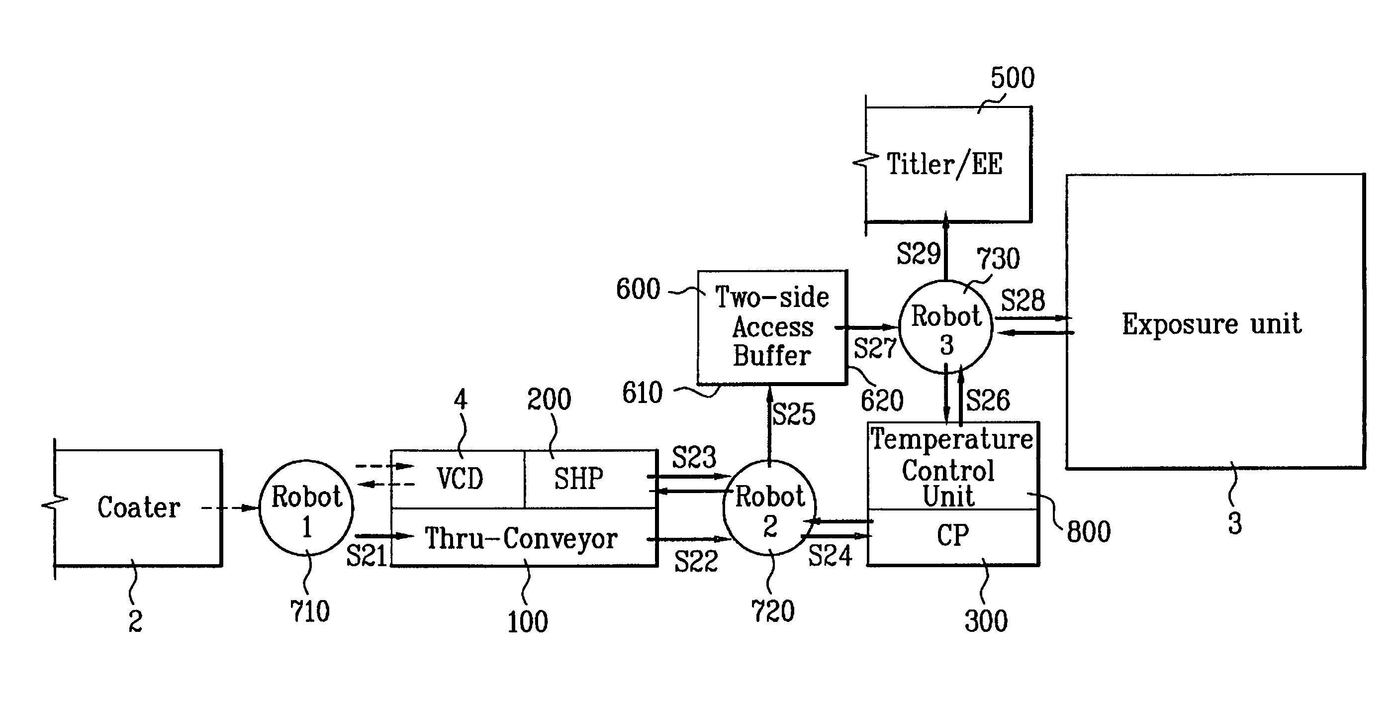
FIG. 2 is a block diagram of an exposure layout according to the

As shown in FIG. 2, an exposure layout according to the first embodiment may include a thru-conveyor 100, a first robot arm 710, a second robot arm 720, a third robot arm 730, a hot plate (solvent removing unit) referred to as a softbake hot plate (SHP) 200, a cool plate 300, a buffer 600, a temperature control unit 800, and an exposure unit 3.

The thru-conveyor 100 may convey a substrate coated with photoresist. Also, the first robot arm 710, the second robot arm 720 and the third robot arm 730 may load and / or unload the substrate. The SHP 200 may remove solvent from the substrate coated with photoresist. Then, the cool plate 300 may receive the substrate from which the solvent is removed, and lowers the temperature of the substrate. After that, the buffer 600 may temporarily store the substrate having the lowered temperature before applying the exposure process to the substrate.

In case of the related art, only one side...

second embodiment

FIG. 3 is a block diagram of an exposure layout according to the

In the exposure layout according to the second embodiment, as shown in FIG. 3, a first robot arm 710, a thru-conveyor 100, a second robot arm 720 and the CP 300 may be sequentially arranged along one line, from a plan view perspective. Also, the temperature control unit 800 and the CP 300 may be provided in two parallel rows. Also, the buffer 600, a third robot arm 730 and an exposure unit 3 may be sequentially arranged along one line. From a plan view perspective, the temperature control unit 800 and the third robot arm 730 may be arranged along the same vertical line. That is, from a plan view perspective, the third robot arm 730 may be positioned over the temperature control unit 800. The buffer 600 and the second robot arm 720 may be arranged along the same line. That is, from a plan view perspective, the buffer 600 may be positioned over the second robot arm 720.

A method for performing the exposure process in the e...


PUM


Abstract

An apparatus for manufacturing a liquid crystal display device is disclosed. A first robot arm at a loading side of the thru-conveyor receives a substrate coated with photoresist and conveys the substrate to a thru-conveyor. A softbake hot plate (SHP) at the unloading side of the thru-conveyor removes solvent from the substrate. A cool plate lowers the substrate temperature from which the solvent is removed. A buffer temporarily stores the substrate having the lowered temperature. A second robot arm between the thru-conveyor, the SHP, the cool plate and a loading side of the buffer, loads / unloads the substrate. A temperature control unit adjusts the substrate temperature unloaded from the buffer. A third robot arm between the unloading side of the buffer, the temperature control unit and an exposure unit that exposes the substrate, loads / unloads the substrate.

Description

This application claims the benefit of Korean Patent Application No. P2004-110197, filed on Dec. 22, 2004, which is hereby incorporated by reference as if fully set forth herein.TECHNICAL FIELDThe present application relates to an apparatus and method for manufacturing a liquid crystal display device, and more particularly, to an exposure layout for applying an exposure process to a substrate of a display device such as a liquid crystal display device.BACKGROUNDGenerally, an exposure unit of an apparatus for manufacturing a liquid crystal display device is provided to perform an exposure process by applying ultraviolet radiation to a glass substrate coated with ph otoresist after providing a photo-mask having a predetermined pattern. Before performing the exposure process, the glass substrate is unloaded from a coating unit for coating the photoresist. At this time, there are a plurality of robot arms and conveyors between the coating unit and the exposure unit for conveying the sub...

Claims


Application Information

Patent Timeline
IPC IPC(8): H01L21/00
CPCH01L21/67184H01L21/67745Y10S414/14Y10S438/942Y10S438/949G02F1/13
Inventor KIM, YONG HUNKWAK, SANG MINSEO, JIN WOO
Owner LG DISPLAY CO LTD
Why Eureka
Try Eureka