Radar device for vehicle and method for adjusting mount angle for mounting radar device on vehicle

a technology for radar devices and vehicles, applied in measurement devices, using reradiation, instruments, etc., can solve the problems of difficult to keep the precision, and the adjusting work of the mount angle has been required a lot of labor, so as to achieve the effect of easy and correct adjustment of the mount angl

Active Publication Date: 2006-07-18
DENSO CORP
View PDF9 Cites 17 Cited by
  • Summary
  • Abstract
  • Description
  • Claims
  • Application Information

AI Technical Summary

Benefits of technology

[0006]The present invention has been implemented in view of the foregoing situation, and has an object to provide a vehicle radar device which can easily and correctly adjust a mount angle at which a reception antenna having plural reception antenna elements arranged in the width direction of a vehicle is mounted on the vehicle, and a method of adjusting the mount angle for mounting the radar device on the vehicle.
[0008]According to the vehicle radar device of the first aspect, the reception beam axis in the vertical direction of at least one reception antenna element is displaced from the reception beam axes of the other antenna elements. Therefore, when the reception beam axes of the reception beams of the other reception antenna elements having the non-displaced beam axes are correctly oriented to a desired direction in the vertical direction with respect to the target, the amplitude (intensity) of the reception signals of the other reception antenna elements having the non-displaced reception beam axes is larger than the amplitude (intensity) of the reception signal of the reception antenna element having the displaced reception beam axis, and thus an amplitude difference occurs therebetween. The magnitude of the amplitude difference varies depending on the orientations of the reception beam axes of the reception antenna elements in the vertical direction. Accordingly, the amplitude difference when the reception beam axes of the reception beams of the reception antenna elements having the non-displaced reception beam axes are correctly oriented to the desired direction with respect to the target is measured in advance, the amplitude difference thus measured is set as a target amplitude difference, and the mount angle of the reception antenna comprising the reception antenna elements is adjusted so that the amplitude difference calculated by the amplitude difference calculator is coincident with the target amplitude difference in the mount angle adjusting work of the reception antenna, whereby the adjustment can be easily and accurately performed.
[0011]The peak of the frequency spectrum calculated by the above method represents the intensity of the reflection wave from the target with high precision. Therefore, the amplitude difference can be accurately calculated by calculating the amplitude difference with the peak of the frequency spectrum as the amplitude of the reception signal. Accordingly, the mount angle of the reception antenna can be accurately adjusted on the basis of the amplitude difference.
[0014]According to a sixth aspect of the invention, the amplitude of the reception signals of the reception antenna elements having the non-displaced reception beam axes is preferably calculated by averaging the reception signals of the reception antenna elements. Accordingly, the S / N ratio is enhanced, and the amplitude difference can be more accurately calculated. According to a seventh aspect of the invention, when the reception signals of the plural reception antenna elements are averaged, the reception signal of the reception antenna element having the displaced reception beam axis may be contained in the reception signals of the plural antenna elements. In this case, some amplitude difference occurs between the amplitude of the reception signal of the reception antenna element having the displaced reception beam axis and the amplitude of the average result of the reception signals of the plural reception antenna elements.
[0015]According to an eighth aspect of the invention, it is preferable that the reception beam axis of a reception antenna element disposed at an end portion of the vehicle in the vehicle width direction is displaced. When the direction to the reflection object is detected, the reception signal of the reception antenna element disposed at the end portion has a smaller effect on the detection of the direction to the reflection object than the reception signals of the antenna elements disposed at the center portion, and thus the effect of the displacement of the reception beam axis can be reduced.
[0016]According to a ninth aspect of the invention, the reception beam axis is displaced so as to direct to the ground surface, and the reflection object detector may use the reception signals of the reception antenna elements having the non-displaced reception beam axes in order to detect reflection objects spaced from the vehicle concerned at a predetermined distance or more and use the reception signal of the reception antenna element having the displaced reception beam axis in order to detect reflection objects existing within a predetermined distance from the vehicle concerned. Accordingly, even when the reception beam axis of the reception antenna element is displaced in the direction to the ground surface, the detection performance of the reflection objects existing at a long distance can be prevented from being lowered. Furthermore, the reception antenna elements for detecting the reflection objects existing at a short distance can be set separately from the reception antenna elements for detecting the long distance reflection objects.

Problems solved by technology

Accordingly, much labor has been hitherto needed to the adjusting work of the mount angle because it is required to keep high precision to make the beam axes coincident with the laser pointer axes, etc., and also it has been hitherto difficult to keep the precision.

Method used


Image

  • Radar device for vehicle and method for adjusting mount angle for mounting radar device on vehicle
  • Radar device for vehicle and method for adjusting mount angle for mounting radar device on vehicle
  • Radar device for vehicle and method for adjusting mount angle for mounting radar device on vehicle

Examples


first embodiment

(First Embodiment)

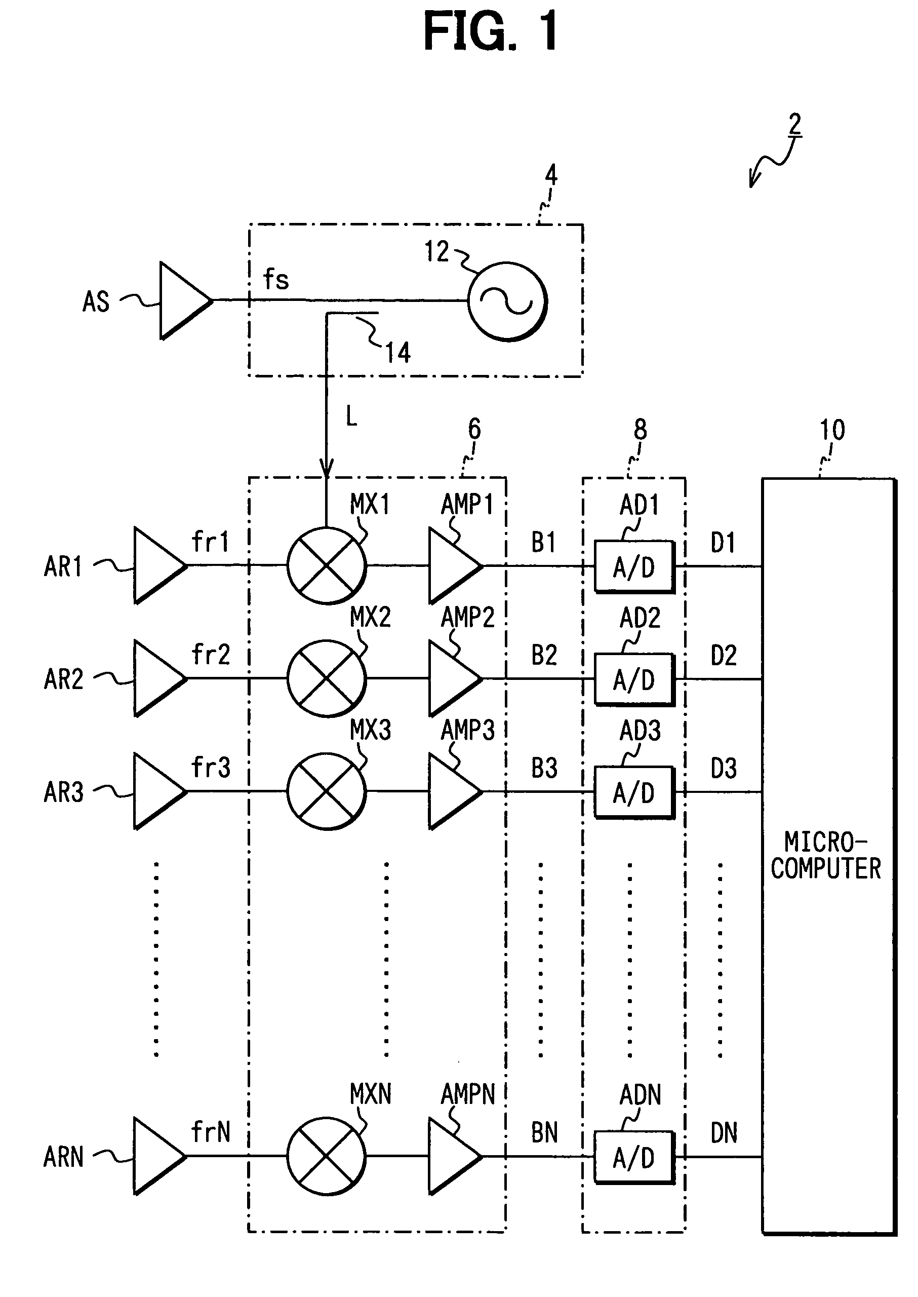
[0032]A first embodiment according to the invention will be described hereunder with reference to the accompanying drawings. FIG. 1 is a block diagram showing the overall construction of a vehicle radar device according to the embodiment.

[0033]As shown in FIG. 1, a radar device 2 according to this embodiment is equipped with a transmitter 4 for transmitting a radar wave in an extremely high frequency band (millimetric-wave band) through a transmission antenna AS. The transmitter 4 comprises a high-frequency oscillator 12 for generating a high-frequency signal of the extremely high frequency band which is modulated so that gradual increase and gradual reduction of the frequency thereof with time lapse are alternately repeated, and a distributor 14 for distributing the power of the output of the high-frequency oscillator 12 to a transmission signal fs and a local signal L. The transmission signal fs is supplied to the transmission antenna AS and the local signal L is...

second embodiment

(Second Embodiment)

[0067]Next, a second embodiment according to the invention will be described. The construction of the radar device according to this embodiment is substantially the same as the first embodiment.

[0068]In this embodiment, the same signal processing as the first embodiment is normally carried out on the reception signals fr1 to frN-1 of the reception antenna elements AR1 to ARN-1 having the non-displaced reception beam axes to calculate the distance D to the reflection object, the relative speed V between the vehicle concerned and the reflection object and the direction to the reflection object. When the distance D to the reflection object is less than a predetermined distance (i.e., short distance), the distance D and the relative speed V between the vehicle concerned and the reflection object are calculated on the basis of the reception signal frN of the reception antenna element ARN.

[0069]The reception beam axis of the reception antenna element ARN is more downwar...


PUM


Abstract

Reception antenna elements are formed so that the reception beam axis in the vertical direction of at least one reception antenna element of a transmission / reception unit is displaced from the reception beam axes of the other antenna elements. Therefore, the amplitude (intensity) of the reception signals of the reception antennas which are caused by a target is different from the amplitude (intensity) of the reception signal of the reception antenna element, and the amplitude difference is varied depending on the orientations of the reception beam axes in the vertical direction of the reception antenna elements. Accordingly, the amplitude difference when the reception beam axes of the reception antenna elements are correctly oriented to a desired direction is measured in advance, and the amplitude difference thus measured is set as a target amplitude difference, whereby the mount angle of the transmission / reception unit can be easily and accurately adjusted.

Description

CROSS REFERENCE TO RELATED APPLICATION[0001]This application is based upon, claims the benefit of priority of, and incorporates by reference the contents of Japanese Patent Application No. 2003-284073 filed on Jul. 31, 2003.FIELD OF THE INVENTION[0002]The present invention relates to a vehicle radar device for detecting target objects existing around a vehicle concerned by transmission / reception of radar waves, and particularly to a technique of adjusting a mount angle at which the vehicle radar device is mounted on the vehicle concerned.BACKGROUND OF THE INVENTION[0003]For example, JP-A-2001-51050 discloses a vehicle radar device comprising a transmission antenna for transmitting a radar wave such as an extremely high frequency wave (millimetric-wave) and a reception antenna having plural antenna elements arranged in the width direction of a vehicle. According to this vehicle radar device, the direction to a forward vehicle (i.e., a vehicle traveling in front of a vehicle having th...

Claims


Application Information

Patent Timeline
Patent Type & Authority Patents(United States)
IPC IPC(8): G01S7/40G01S13/93G01S13/34G01S13/48G01S13/60G01S13/931
CPCG01S7/4026G01S2007/4086G01S2007/4034G01S13/931G01S7/4034G01S7/4086
Inventor FUJITA, AKIHISA
Owner DENSO CORP
Why Eureka
Try Eureka