Method and system for implementing multiple high precision and low precision interpolators for a graphics pipeline

Active Publication Date: 2006-07-18
NVIDIA CORP
View PDF6 Cites 22 Cited by
  • Summary
  • Abstract
  • Description
  • Claims
  • Application Information

AI Technical Summary

Benefits of technology

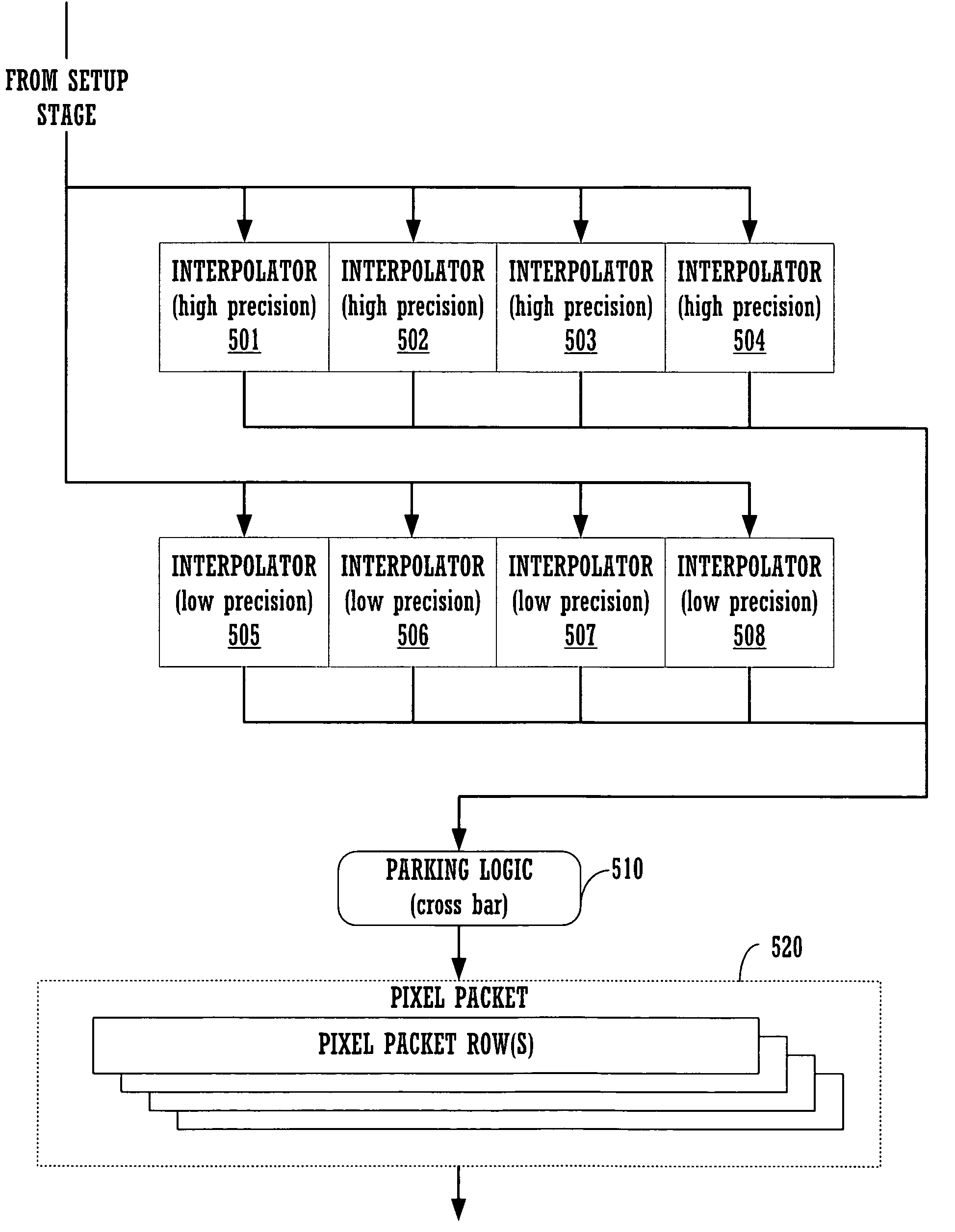
[0013]In one embodiment, the plurality of interpolators of the raster stage are configured to use Barycentric coordinates to interpolate parameters for each pixel of a polygon. By using Barycentric coordinates, the interpolators can be impleme

Problems solved by technology

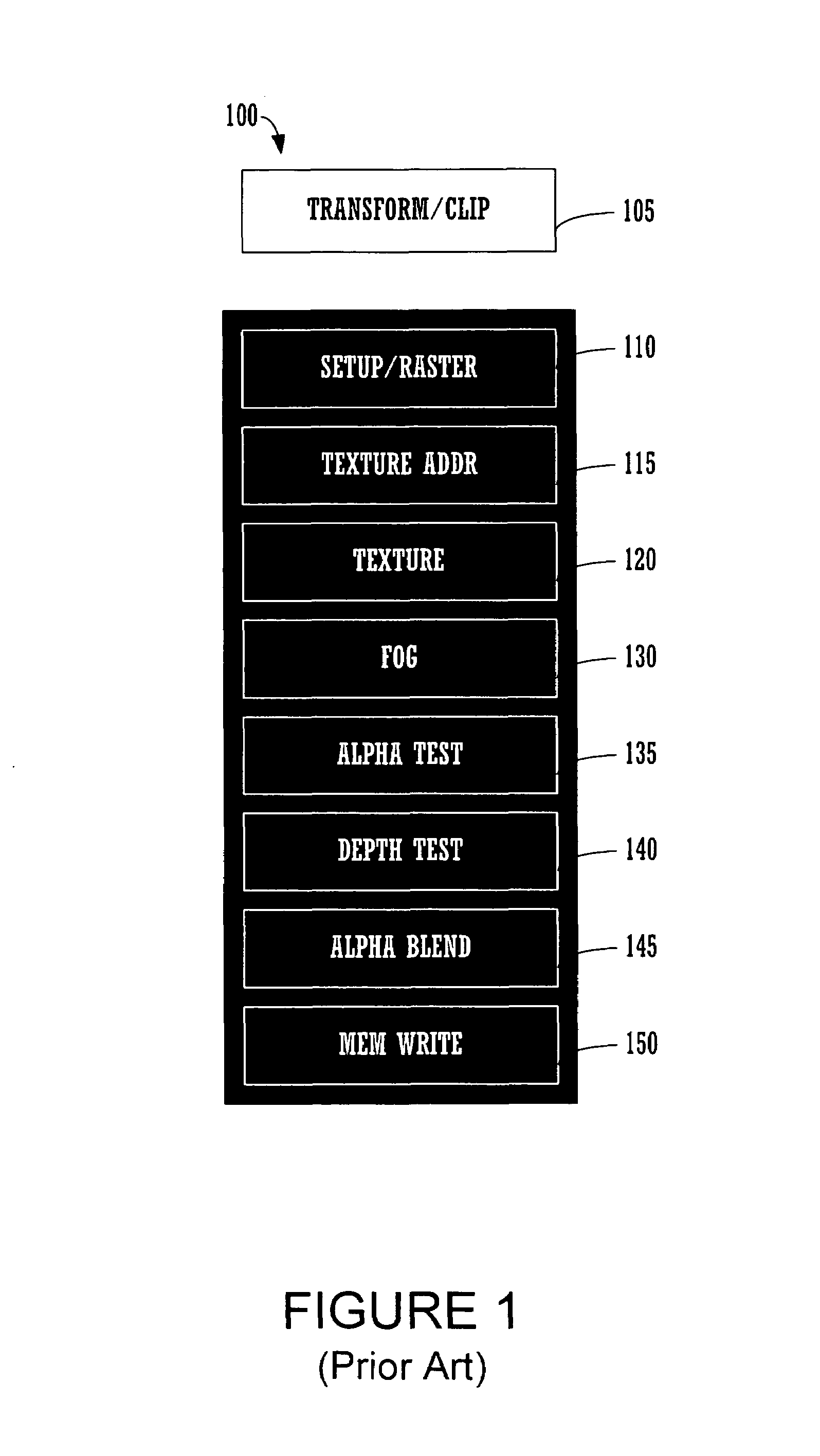
However, the traditional deep pipeline architecture requires a significant chip area, resulting in greater cost than desired.
Additionally, a deep pipeline consumes significant power, even if the stages are performing comparatively little processing.
This is because many of the stages consume about the same amount of power regardless of whether they are processing pixels.
As a result of cost and power considerations, the conventional deep pipeline architecture illustrated in FIG. 1 is unsuitable for many

Method used


Image

  • Method and system for implementing multiple high precision and low precision interpolators for a graphics pipeline
  • Method and system for implementing multiple high precision and low precision interpolators for a graphics pipeline
  • Method and system for implementing multiple high precision and low precision interpolators for a graphics pipeline

Examples


Embodiment Construction

[0036]Reference will now be made in detail to the preferred embodiments of the present invention, examples of which are illustrated in the accompanying drawings. While the invention will be described in conjunction with the preferred embodiments, it will be understood that they are not intended to limit the invention to these embodiments. On the contrary, the invention is intended to cover alternatives, modifications and equivalents, which may be included within the spirit and scope of the invention as defined by the appended claims. Furthermore, in the following detailed description of embodiments of the present invention, numerous specific details are set forth in order to provide a thorough understanding of the present invention. However, it will be recognized by one of ordinary skill in the art that the present invention may be practiced without these specific details. In other instances, well-known methods, procedures, components, and circuits have not been described in detail ...


PUM


Abstract

A rasterizer stage configured to implement multiple interpolators for graphics pipeline. The rasterizer stage includes a plurality of simultaneously operable low precision interpolators for computing a first set of pixel parameters for pixels of a geometric primitive and a plurality of simultaneously operable high precision interpolators for computing a second set of pixel parameters for pixels of the geometric primitive. The rasterizer stage also includes an output mechanism coupled to the interpolators for routing computed pixel parameters into a memory array. Parameters may be programmably assigned to the interpolators and the results thereof may be programmably assigned to portions of a pixel packet.

Description

CROSS REFERENCE TO RELATED APPLICATIONS[0001]This application is related to, and incorporates by reference, the following commonly assigned U.S. patent applications:A METHOD AND SYSTEM FOR IMPLEMENTING CLAMPED Z VALUE INTERPOLATION IN A RASTER STAGE OF A GRAPHICS PIPELINE, by Ed Hutchins, filed on May 14, 2004, Ser. No. 10 / 845,992;A METHOD AND SYSTEM FOR IMPLEMENTING PARAMETER CLAMPING TO A VALID RANGE IN A RASTER STAGE OF A GRAPHICS PIPELINE, by Ed Hutchins, filed on May 14, 2004, Ser. No. 10 / 845,987;METHOD AND SYSTEM FOR COMPUTING PIXEL PARAMETERS, by Ed Hutchins, filed on May 14, 2004, Ser. No. 10 / 846,771; andMETHOD AND SYSTEM FOR A GENERAL INSTRUCTION RASTER STAGE THAT GENERATES PROGRAMMABLE PIXEL PACKETS, by Ed Hutchins et al., filed on May 14, 2004, Ser. No. 10 / 845,642.FIELD OF THE INVENTION[0002]The present invention is generally related to computer implemented graphics. More particularly, embodiments of the present invention are directed towards low power programmable proces...

Claims


Application Information

Patent Timeline
IPC IPC(8): G09G5/00
CPCG06T15/005G06T11/40
Inventor HUTCHINS, EDWARD A.ANGELL, BRIAN K.
Owner NVIDIA CORP
Why Eureka
Try Eureka