Private network link verification procedure in free space optical communication network

Inactive Publication Date: 2006-07-18
INTELLECTUAL VENTURES FUND 83 LLC
View PDF16 Cites 38 Cited by
  • Summary
  • Abstract
  • Description
  • Claims
  • Application Information

AI Technical Summary

Benefits of technology

[0009]A node for use in a freespace optical communication network, wherein the node comprises a plurality of node heads. Each node head comprises an optical receiver and an optical transmitter, and a node base. The node base is coupled with the plurality of node heads, and comprises a control processor and a data transport mechanism switch, wherein the switch is coupled to the control processor and said plurality of node heads. The control processor includes a link verification module for monitoring and verifying the status of a communication link between nodes in the network.
[0010]The control processor can further comprise a first state variable configured to indicate the status of a physical layer, a physical layer task configured to monitor the first state variable, and a physical layer interrupt service routine configured to control the physical layer task and report physical layer events to the link verification module. Also included in the control processor are a second state variable configured to indicate the status of a transceiver layer, a transceiver task configured to monitor the second state variable, a link maintenance protocol configured to receive reporting of transceiver events via the transceiver task, and a transceiver manager task module configured to report transceiver layer events to the link verification module.
[0011]A method for verifying the status of a communication link in a wireless communication network having a plurality of nodes with optical communication links therebetween, wherein the optical communication link is implemented using an optical receiver/transmitter pair, wherein the receiver/transmitter pair has a physical layer and a receiver/transmitter layer. The method comprises checking the status of the receiver/transmitter layer for changes in the status of the communication link at the receiver/transmitter layer. And if the checking results in a link-up status, then the method further comprises notifying a link verification module of the link up status, checking the status of the physical layer for stability via a physical layer link up procedure, and enabling network signaling over the communication link if the physical layer is stable. If, when checking the status of the receiver/transmitter layer results in a link down status the method further comprises notifying a link verification module of the link down status and disabling network signaling over the communication link.
[0012]A method for verifying the status of a communication link in a wireless communi

Problems solved by technology

However, many homes and offices do not have a practical solution to interface to these backbone networks.
Consequently, direct attachment of potential customers to these backbone networks remains very expensive.
However, both of these methods incur significant up-front costs before any revenue can be realized.
In the case of buried or aerial fiber, these costs are associated with obtaining rights-of-way for the cable runs, and installing the cable by burying or hanging.
In the case of a microwave system, these up front

Method used


Image

  • Private network link verification procedure in free space optical communication network
  • Private network link verification procedure in free space optical communication network
  • Private network link verification procedure in free space optical communication network

Examples


Embodiment Construction

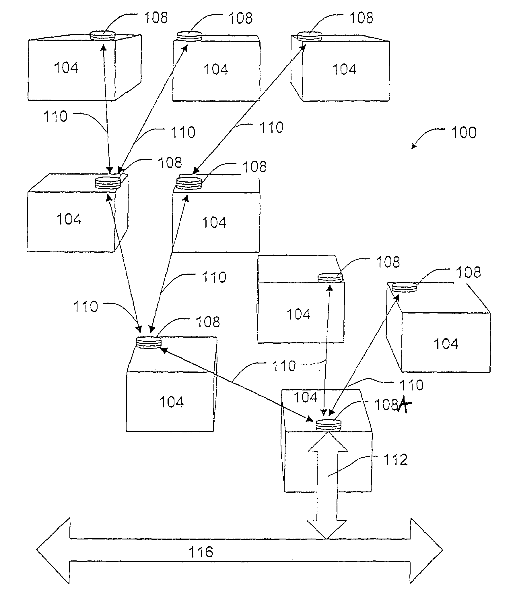
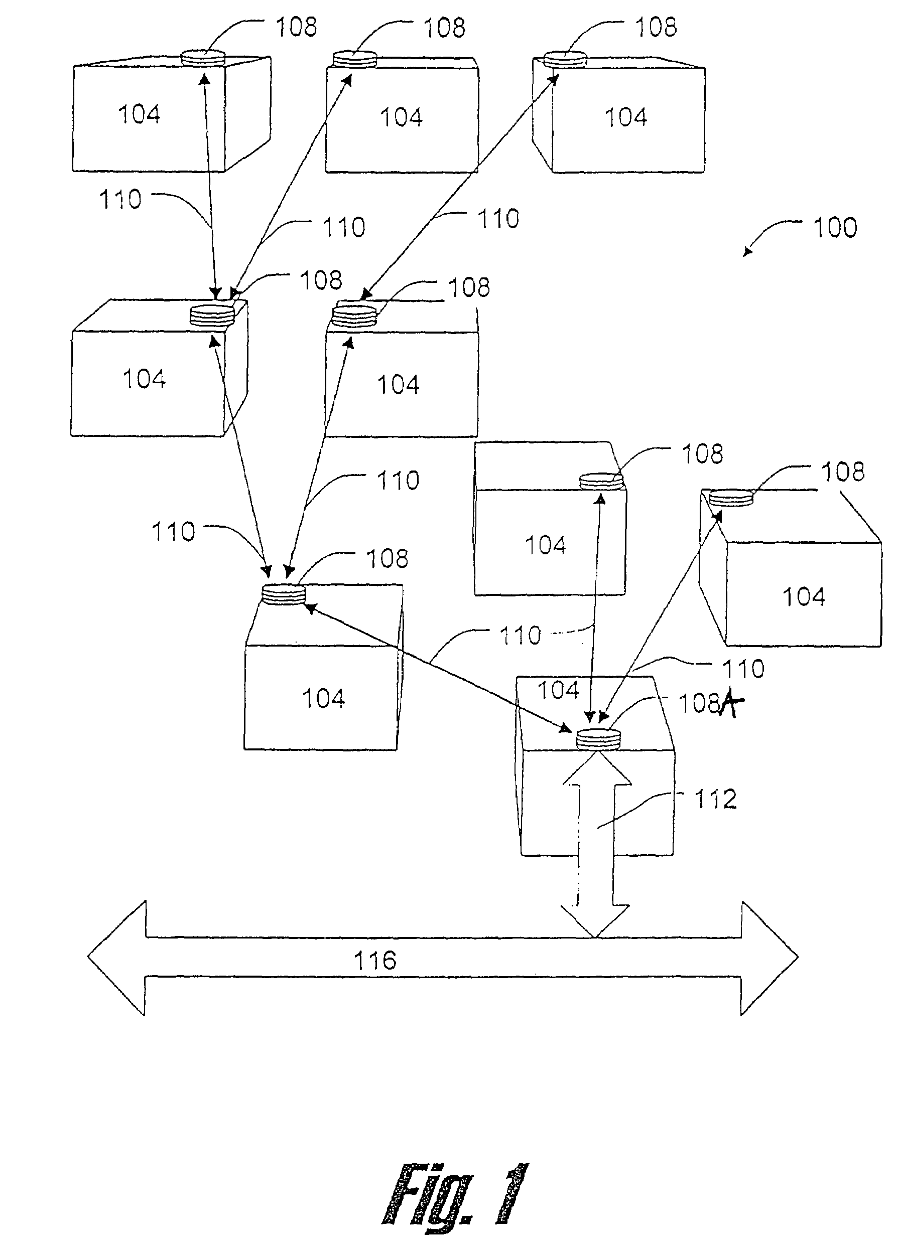
[0029]FIG. 1 is a diagram illustrating an example communication network 100. The communication network 100 illustrated in FIG. 1 can include a plurality of nodes 108, interconnected by communication links 110. The network nodes 108 are disposed on facilities 104. Although only one node 108 is provided per facility in the example illustrated in FIG. 1, more than one node 108 can be provided at one or more of facilities 104 depending on the communication requirements of the particular facility.

[0030]In exemplary embodiments of the network system, the facilities 104 can be buildings, towers, or other structures, premises, or locations. The facilities 104 can, for example, be homes or offices to which it is desirable to interface one or more backbone networks of one or more common carriers or service providers. In these embodiments, the network 100 can provide the interface between the facilities 104 and the backbone network.

[0031]The nodes 108 can be interconnected with one another by ...


PUM


Abstract

A system and method for verifying the integrity of a communication link in a wireless optical communication network. The system and method include monitoring the communication link on at least two levels and enabling or disabling signaling over the communication link appropriately depending on events reported through the system.

Description

CROSS REFERENCE TO RELATED APPLICATION[0001]This application claims priority to U.S. Provisional patent application 60 / 238,326 entitled “PNNI LINK VERIFICATION (PLV) PROCEDURE” and filed on Oct. 5, 2000. The disclosure of the above-described filed application is hereby incorporated by reference in its entirety.BACKGROUND OF THE INVENTION[0002]1. Field of the Invention[0003]The present invention relates generally to communication systems, and to a system and method for verifying a communication link for a communication network.[0004]2. Description of the Related Art[0005]Over the last several years there has been tremendous growth in the deployment of fiber-optic facilities by telecommunications carriers such as Regional Bell Operating Companies (RBOCs), cable carriers, and Competitive Local Exchange Carriers (CLECs). Deployment of these facilities along with the introduction of technologies such as OC-192 and Dense Wave Division Multiplexing (DWDM) has dramatically lowered the margi...

Claims


Application Information

Patent Timeline
IPC IPC(8): G06F15/173G01R31/08H04L12/28H04B10/10H04Q11/00
CPCH04B10/1149H04Q11/0062H04W12/10H04W24/00H04Q2011/0086H04Q2011/0083
Inventor SHIVNAN, AINE
Owner INTELLECTUAL VENTURES FUND 83 LLC
Why Eureka
Try Eureka