Method and system for recovering information from a magnetic field signal usable for locating an underground object

Active Publication Date: 2006-07-18
RADIODETECTION
View PDF10 Cites 52 Cited by
  • Summary
  • Abstract
  • Description
  • Claims
  • Application Information

AI Technical Summary

Problems solved by technology

Thus, the reliability and accuracy of such location determinations can be adversely affected when the magnetic field measurements are corrupted.
More specifically, the location determinations can be adversely affected at the monitoring device.
The primary sources of magnetic field interference in this environment are power distribution networks.
Besides adversely affecting the reliability and accuracy of location determinations, magneti

Method used


Image

  • Method and system for recovering information from a magnetic field signal usable for locating an underground object
  • Method and system for recovering information from a magnetic field signal usable for locating an underground object
  • Method and system for recovering information from a magnetic field signal usable for locating an underground object

Examples


Embodiment Construction

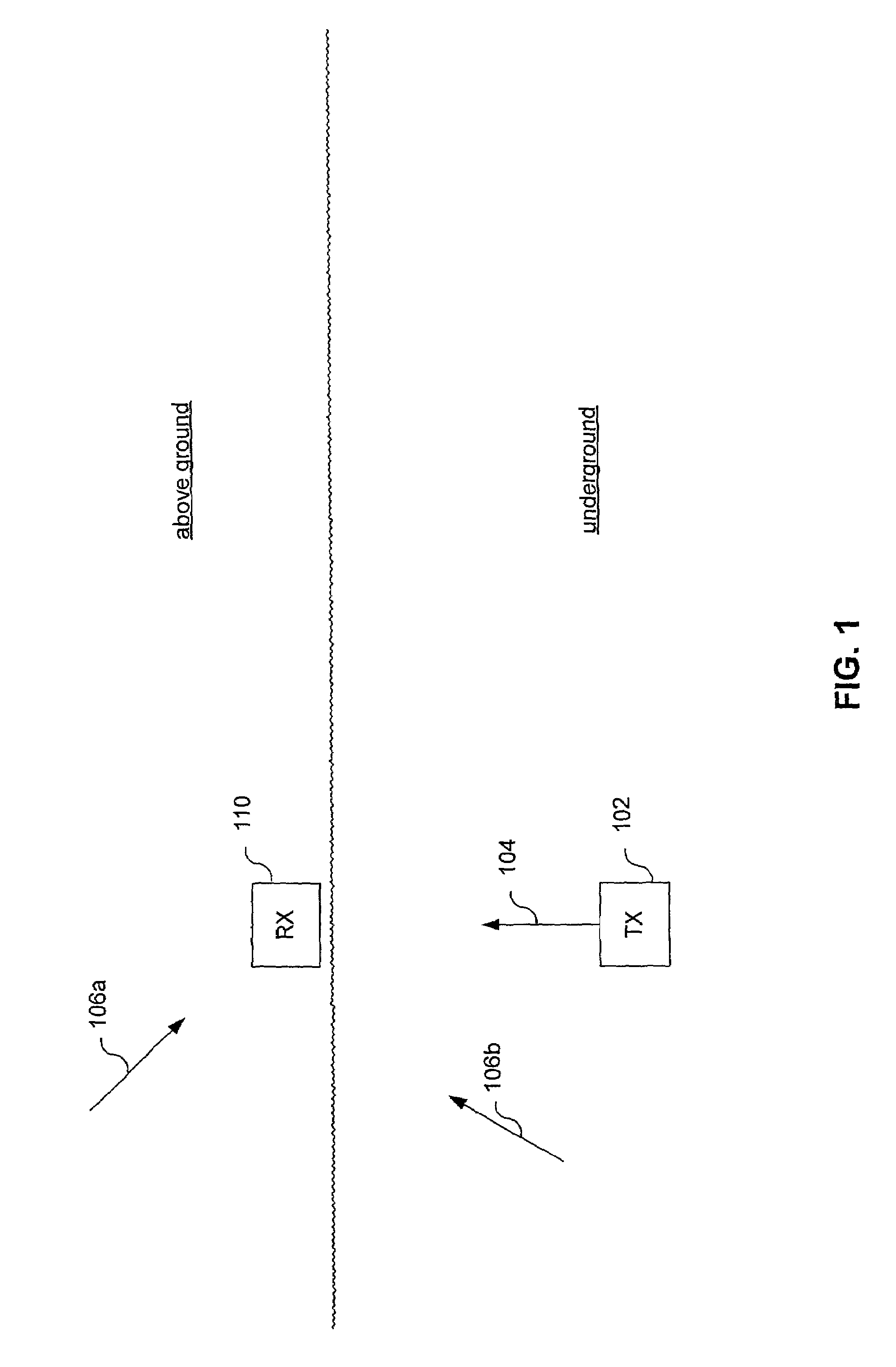
[0037]Prior to explaining specific details of the present invention, an exemplary environment where the present invention is useful will first be described. Referring to FIG. 1, an underground transmit device 102 transmits a magnetic field signal 104 that can be received by a receive / monitoring device 110. Transmit device 102 is typically mounted to, or integrally formed with, a boring / drilling tool (not shown in FIG. 1). Receive device 110 is typically part of, or in communications with, a monitoring device that monitors, among other things, a location of transmit device 102 (and thereby, a location of the boring tool). As will be explained below, receive device 110 determines the location of transmit device 102 based on a received magnetic field signal (including magnetic field signal 104 generated by transmit device 102). As will also be explained in more detail below, the monitoring device can determine additional information, when magnetic field signal 104 is modulated to conve...


PUM


Abstract

A data recovery subsystem for use in a receive system configured to receive a magnetic field signal, the magnetic field signal including a carrier component usable for locating an underground object and at least one modulation sideband. The data recovery subsystem includes a first mixer to mix a Radio Frequency (RF) signal with a first Local Oscillator (LO) signal to produce an Intermediate Frequency (IF) signal representative of the magnetic field signal. A Phase Locked Loop (PLL) phase-locks a second LO signal to an IF carrier component of the IF signal. A second mixer synchronously mixes the IF signal with the second LO signal to produce a baseband signal including a demodulated sideband.

Description

FIELD OF THE INVENTION[0001]The present invention is directed to a method and system for recovering information from a magnetic field signal, the magnetic field signal including a magnetic field carrier component usable for locating an underground object such as a boring tool, and at least one magnetic field signal modulation sideband that conveys the information to be recovered.BACKGROUND OF THE INVENTION[0002]Several guided and unguided sub-surface (i.e., underground) boring tools are currently on the market. Guided tools require substantially continuous location and orientation monitoring to provide necessary steering information. To monitor such an underground tool it is necessary to track the sub-surface location of the tool. Only once the location of the tool is located can a proper depth measurement be obtained, for example, from a measuring position directly above the head of the boring tool which houses a transmitter. Unguided tools would also benefit from periodic locating...

Claims


Application Information

Patent Timeline
IPC IPC(8): H03K9/00H03D3/24G01V3/08H03D7/16
CPCG01V3/08H03D7/163H03D3/242
Inventor FLING, RICHARD W.LANFRANCHI, LUIGI
Owner RADIODETECTION
Why Eureka
Try Eureka