Optical communication system, optical communication apparatus, and optical cable

a communication system and optical communication technology, applied in the direction of transmission monitoring, coupling device connection, ways, etc., can solve the problems of inability to detect the extraction and the inability to stop the emission of light from the light emitting element, and achieve the effect of enabling control of light emission

Inactive Publication Date: 2006-07-18
SONY CORP
View PDF6 Cites 23 Cited by
  • Summary
  • Abstract
  • Description
  • Claims
  • Application Information

AI Technical Summary

Benefits of technology

[0029]Thus, by monitoring the state of conduction of the detection circuit by means of the monitor in the first optical communication apparatus, it is possible to detect not only that the optical cable is extracted from any one of the first and second optical communication apparatuses, but also that the optical cable is broken.
[0030]Therefore, the optical communication system according to the invention allows output of the light emitter to be controlled, for example, emission of light therefrom to stop or a quantity of emitted light to be suppressed not only if the optical cable is extracted from any one of the first and second optical communication apparatuses, but also if the optical cable is broken.
[0031]Thus, the optical communication system according to the present invention prevents light from being leaked out of the optical communication apparatus from which the optical cable is extracted or from the optical cable where it is broken, thereby improving safety. The system also suppresses dissipation power because emission of light is stopped or suppressed if communication is disabled.

Problems solved by technology

However, if the optical fiber cable is extracted from the other optical communication apparatus or if it is broken, the extraction cannot be detected.
This has brought about a problem that if the optical fiber cable is extracted from the other optical communication apparatus or if it is broken, it is impossible to stop emission of light from the light emitting element.

Method used


Image

  • Optical communication system, optical communication apparatus, and optical cable
  • Optical communication system, optical communication apparatus, and optical cable
  • Optical communication system, optical communication apparatus, and optical cable

Examples


first embodiment

[0055]An optical communication system 1 of the first embodiment has such a configuration that an optical communication apparatus 2 and the other optical communication apparatus 3 are coupled to each other through an optical fiber cable 4, to realize a unidirectional optical communication. The optical fiber cable 4 is one example of an optical cable and, as shown in FIG. 5, has an optical fiber core 4a through which an optical signal is ID propagated and a coating 4b for protecting this optical fiber core 4a. The optical fiber cable 4 is provided with two conducting wires 5 and 6 along this optical fiber core 4a. The conducting wires 5 and 6 constitutes inter-apparatus conductor and electrically interconnects the optical communication apparatuses 2 and 3 coupled to each other by the optical fiber cable 4.

[0056]The optical communication apparatus 2 comprises an output-side conducting circuit 7 connected to the conducting wires 5 and 6. The optical communication apparatus 3, on the oth...

second embodiment

[0090]An optical communication system 21 of the second embodiment has such a configuration that an optical communication apparatus 22 and the other optical communication apparatus 23 are coupled to each other through an optical fiber cable 4, to realize a single-core bi-directional optical communication. Although the optical communication apparatus 22 is shown in FIG. 8, the optical communication apparatus 23 has the same configuration.

[0091]The optical fiber cable 4 has the same configuration as that described concerning the optical communication system 1 of the first embodiment in that one optical fiber core 4a through which an optical signal is propagated is covered by a coating 4b. The optical fiber cable 4 has two conducting wires 5 and 6 along this optical fiber core 4a. The wires electrically interconnect the optical communication apparatuses 22 and 23 coupled to each other through the optical fiber cable 4.

[0092]The optical communication apparatus 22 comprises an output-side...

third embodiment

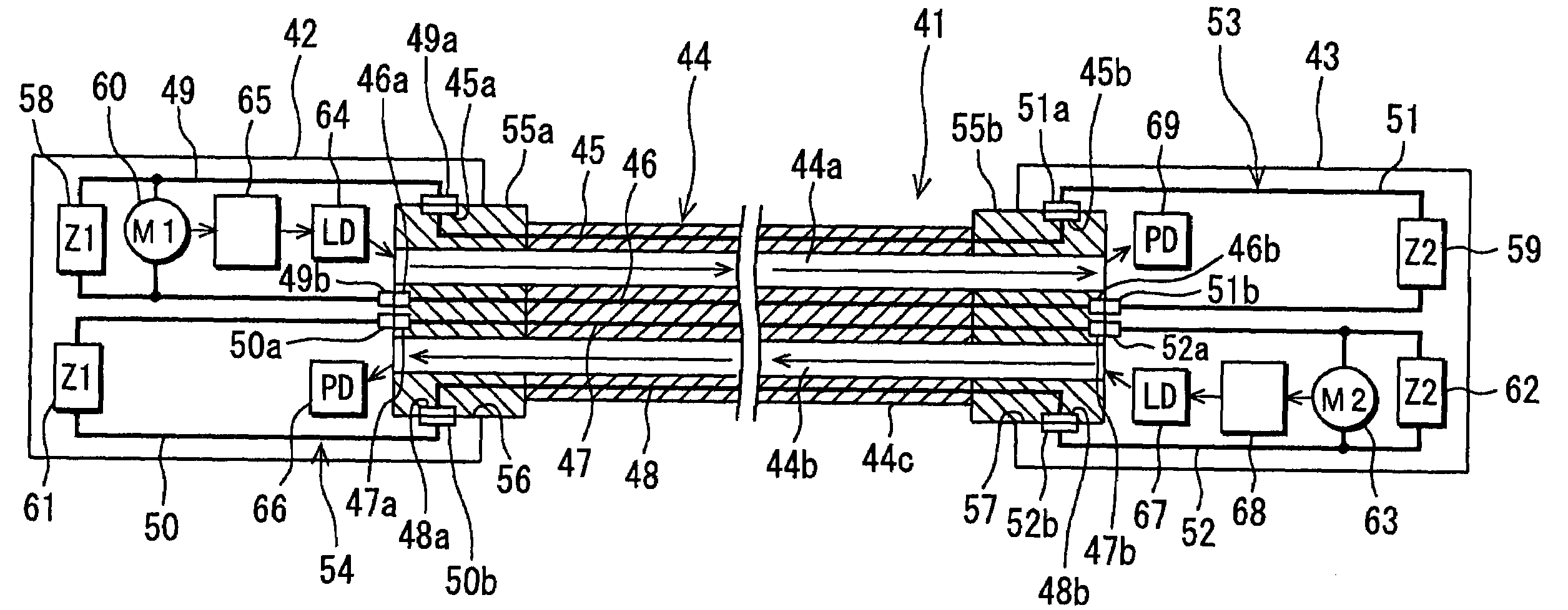
[0138]An optical communication system 41 of the third embodiment has such a configuration that an optical communication apparatus 42 and an optical communication apparatus 43 are coupled to each other through an optical fiber cable 44, to realize a multi-core bi-directional optical communication. Although the optical communication apparatus 42 is shown in FIG. 11, the optical communication apparatus 43 has the same configuration as that of the optical communication apparatus 42.

[0139]The optical fiber cable 44 is one example of an optical cable and, as shown in FIG. 12, has a configuration that a coating 44c covers two optical fiber cores 44a and 44b through which an optical signal is propagated. The optical fiber cable 44 includes four conducting wires 45, 46, 47, and 48 along these optical fiber cores 44a and 44b. The conducting wires 45, 46, 47, and 48 constitute the inter-apparatus conductor and electrically interconnect the optical communication apparatuses 42 and 43 coupled to...


PUM


Abstract

An optical communication apparatus is connected to the other communication apparatus by an optical fiber. The optical fiber cable comprises conducting wires. By interconnecting an output-side conducting circuit provided to the optical communication apparatus and an input-side conducting circuit provided to the other communication apparatus, a detection circuit is constituted. The optical communication apparatus comprises a monitor for monitoring a state of conduction of the detection circuit and an output control portion for controlling a laser diode. When the optical fiber cable is extracted from the optical communication apparatus, it is extracted from the other communication apparatus, and it is broken, the output-side and input-side conducting circuits are cut off. The monitor monitors a change in the state of conduction. If the monitor detects a change in the state of conduction, the output control portion stops emission of light from the laser diode.

Description

BACKGROUND OF THE INVENTION[0001]1. Field of the Invention[0002]The present invention relates to an optical communication system in which one optical communication apparatus and another are coupled to each other by an optical cable and the optical communication apparatus and the optical cable that constitute this optical communication system.[0003]2. Description of Related Art[0004]In an optical communication system in which optical communication apparatus that is equipped with a light emitting element for outputting an optical signal and a light receiving element for receiving the optical signal is coupled to another by an optical fiber cable, the optical fiber cable can be attached to and detached from the optical communication apparatus.[0005]In the optical communication apparatus, as far as power is applied to them, for example, the light emitting element continues to emit light. Therefore, even if the optical fiber cable is not coupled to the optical communication apparatus, th...

Claims


Application Information

Patent Timeline
Patent Type & Authority Patents(United States)
IPC IPC(8): G02B6/44H01R33/945H04B10/08H04B10/07H04B10/079H04B17/00
CPCG02B6/4416H04B10/0791H04B2210/08E01C23/127
Inventor TORIUMI, YOICHITSUKAHARA, NOBUHIKO
Owner SONY CORP
Why Eureka
Try Eureka