Hydraulic cylinder

a technology of hydraulic cylinders and cylinder heads, applied in the direction of machines/engines, servomotor components, servomotors, etc., can solve the problem of very restricted “handling” work of operators, and achieve the effect of less cos

Inactive Publication Date: 2006-07-25
BTM CORP
View PDF7 Cites 4 Cited by
  • Summary
  • Abstract
  • Description
  • Claims
  • Application Information

AI Technical Summary

Benefits of technology

[0005]Known in addition is a press which uses an internal path-measuring system in order to allow, after calibration, the power stroke to be reduced or first set to 6 mm. Other accomplishments consist for example of a hinged mechanism, covering the region endangering the hands of the operator and only allowing the power stroke when in the folded state. Likewise known is a device with powerless partial thrust, which is characterized in that the drive of the thrust used therein is effected pneumatically and is limited to a total stroke of 60 mm. Another accomplishment consists in avoiding violation of the safety distance of 6 mm by limiting the speed of thrust to a prescribed amount, in order to ensure timely removal / withdrawal of the operator's limbs.
[0006]It is the object of the invention to propose a hydraulic cylinder which avoids the complicated and costly precautions known in the prior art as much as possible.
[0007]This object is accomplished by a hydraulic cylinder as described herein. By this means, an additional control circuit, be it pneumatic, electrical, mechanical or a combination thereof, advantageously becomes superfluous. The device, with like operating safety, thereby becomes substantially less costly than known systems. Here, the medium (e.g. hydraulic oil) which is used for the development of power is at the same time the medium for the safety shut-off. Other media, such as water or the like, for example, are alternatively usable here. An additional advantage consists in that the device according to the invention is not limited to a total stroke. Theoretically, all desired strokes technically producible can be executed. In addition, the device according to the invention also has the advantage that it is not limited to a maximum speed of movement. The thrust as well as the power stroke speeds are freely selectable with use of the device according to the invention, provided that the technical provisions (existing volumetric flow, feed-line cross sections, etc.) permit this. In addition, with the device according to the invention an internal anti-twisting means advantageously can be integrated with the device according to the invention and via a continuous piston rod an external adjustable full-stroke limitation can be built on, which makes it possible to limit the return stroke of the piston / ram, and hence the full stroke, in any desired position, in simple fashion.

Problems solved by technology

As a result, the operator is very restricted in “handling” work in the dangerous region of the ram of a corresponding deforming or joining device.

Method used


Image

  • Hydraulic cylinder
  • Hydraulic cylinder
  • Hydraulic cylinder

Examples


Embodiment Construction

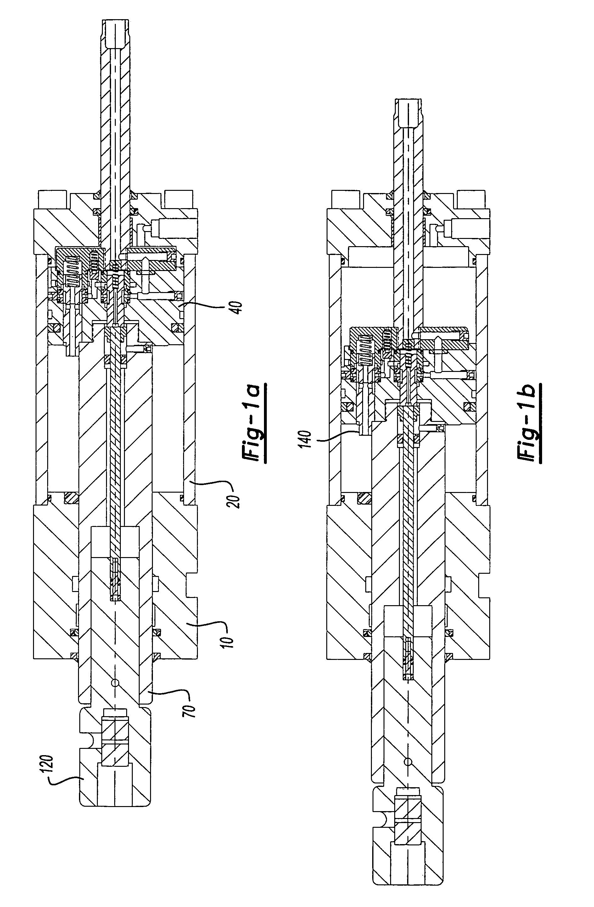
[0014]The representations in FIG. 1 show the following working positions: Position a shows the starting position. Position b shows the shut-off position, in which an obstacle in the planned path of travel of the extended piston rod of the cylinder is encountered. Position c shows a hydraulic cylinder with fully extended piston rod after ending the complete power stroke.

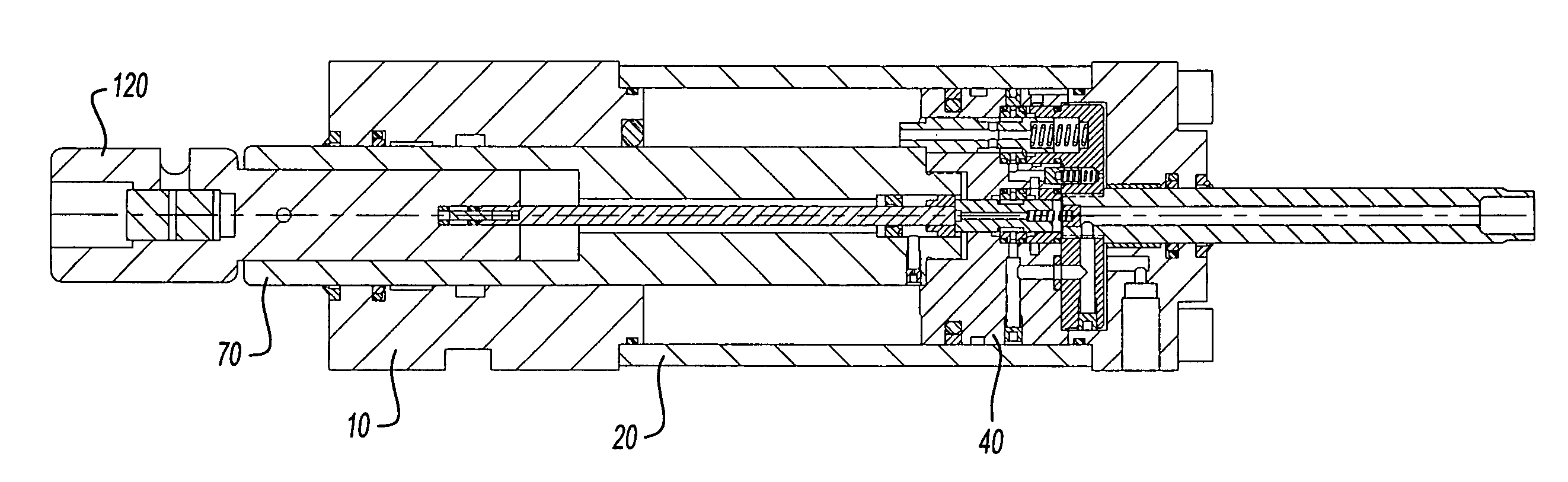
[0015]The operating routine of the work program of the hydraulic cylinder according to the invention will be described with the aid of the figures. The positions of the components of the hydraulic cylinder according to the invention shown in FIGS. 1a, 2a and b as well as 3 indicate the starting position (position a). Here, a piston 40 is found in the outermost right-hand position in a partially shown cylinder housing 10. The piston 40, to which is assigned a piston rod 70, is axially displaceable in the cylinder housing 10. In the piston rod 70 is located a so-called tool-receiving element 120, which is axially displa...


PUM


Abstract

The invention relates to a hydraulic cylinder comprising a piston rod bearing at least one tool receiving element. Said hydraulic cylinder is characterized by an automatic disconnection device which is controlled in a hydraulic-mechanical manner, with a medium for the actuation of the hydraulic cylinder. Said medium which is used for building-up force, is also the medium which is used for the automatic disconnection device. Said hydraulic cylinder also comprises a first valve slider and a second valve slider which are used for disconnecting the displacement of a piston, which is connected to a piston rod according to a possible obstruction found in the path of the outward moving piston rod before a desired position by deviating the medium in the region of the piston.

Description

CROSS-REFERENCE TO RELATED APPLICATIONS[0001]This application is a continuation of PCT Ser. No. PCT / EP2003 / 007538, filed Jul. 11, 2003, which claims priority to German Application No. 102 33 669.5, filed Jul. 24, 2002, both of which are incorporated by reference herein.BACKGROUND AND SUMMARY OF THE INVENTION[0002]The present invention relates to a hydraulic cylinder having a piston rod bearing a tool-receiving element.[0003]Usually, because of the pressing force required, hydraulic drives having hydraulic cylinders are used for mechanical deforming or joining processes, such as for example punching, stamping, flanging, crimping, riveting or clinching. For safety reasons, when the power stroke of hydraulic cylinders is more than 6 mm, great safety requirements are placed on the systems used. Thus, for avoiding risks, complicated protective curtains and / or mechanical, pneumatic or electrical interlocking devices must be provided. As a result, the operator is very restricted in “handli...

Claims


Application Information

Patent Timeline
Patent Type & Authority Patents(United States)
IPC IPC(8): F15B15/26F15B15/20F15B20/00
CPCF15B20/00F15B15/204
Inventor BEULE, ULRICH
Owner BTM CORP
Why Eureka
Try Eureka