Pivoting feed roller

a feed roller and feed roller technology, applied in the field of sewing machines, can solve the problems of affecting affecting the sewing machine, so as to reduce the cost of purchasing a sewing machine, reduce the cost of maintenance, and increase the reliability of the sewing machin

Inactive Publication Date: 2006-07-25
NAT FLOORING EQUIP INC
View PDF7 Cites 11 Cited by
  • Summary
  • Abstract
  • Description
  • Claims
  • Application Information

AI Technical Summary

Benefits of technology

[0021]It is an object of the invention to prevent floating of one roller over the top of uneven material.
[0022]It is an object of the invention to reduce maintenance costs.
[0023]It is an object of the invention to reduce the cost of purchasing a sewing machine.
[0024]It is an object of the invention to increase reliability of the sewing machine.
[00

Problems solved by technology

Problems arise when the material to be sewn is of uneven thickness since one roller will be pressing down on the material too hard and apply too much force on the material while the other roller is floating above the material providing little or no traction, thus causing bunching of the material between the rollers.
This may cause an uneven feed resulting in jamming or uneven stitching.
The separately driven rollers require separate gears and clutches which take up space and therefore space the rollers further apart.
As the rollers are moved further apart the

Method used


Image

  • Pivoting feed roller
  • Pivoting feed roller
  • Pivoting feed roller

Examples


Embodiment Construction

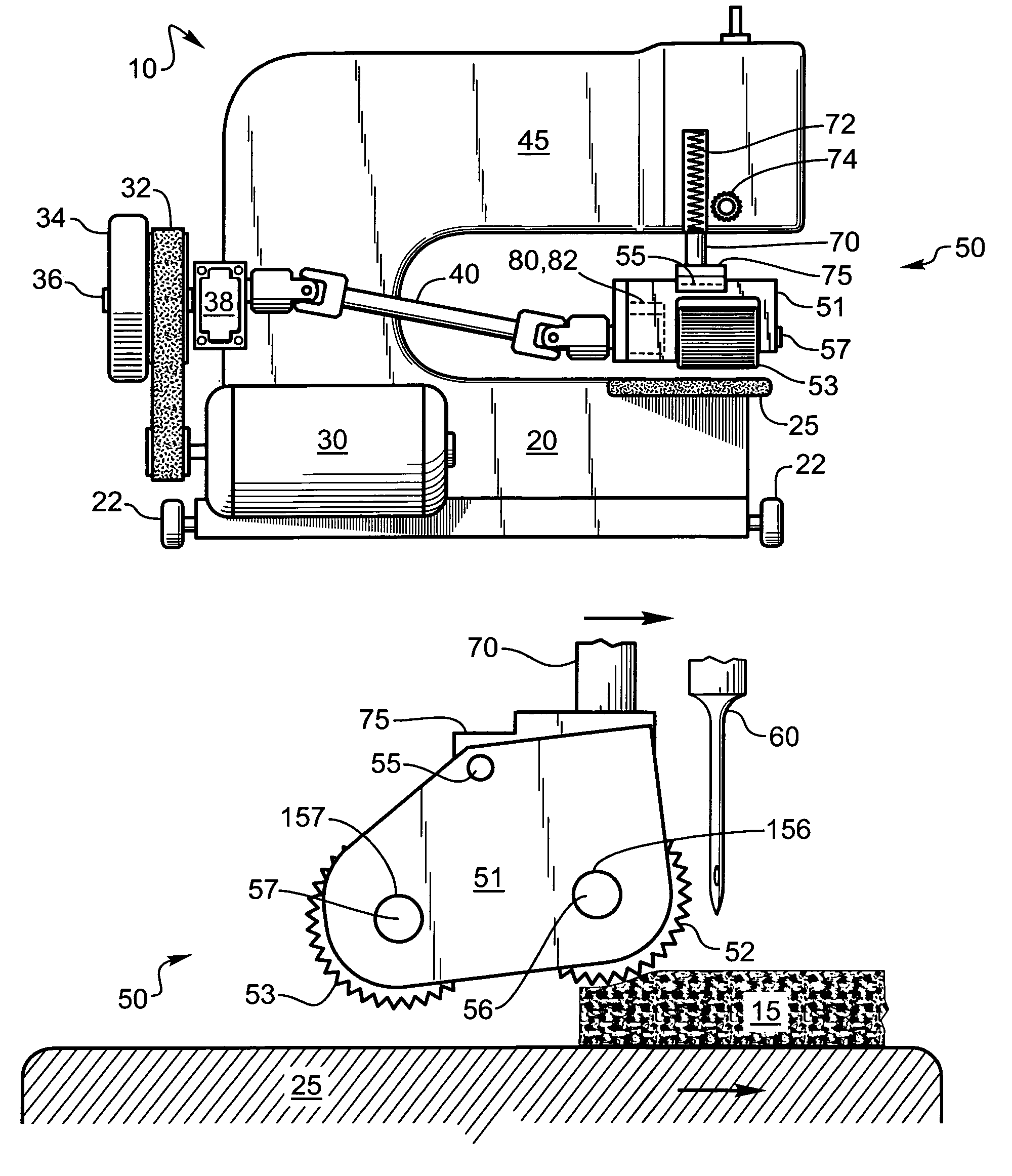
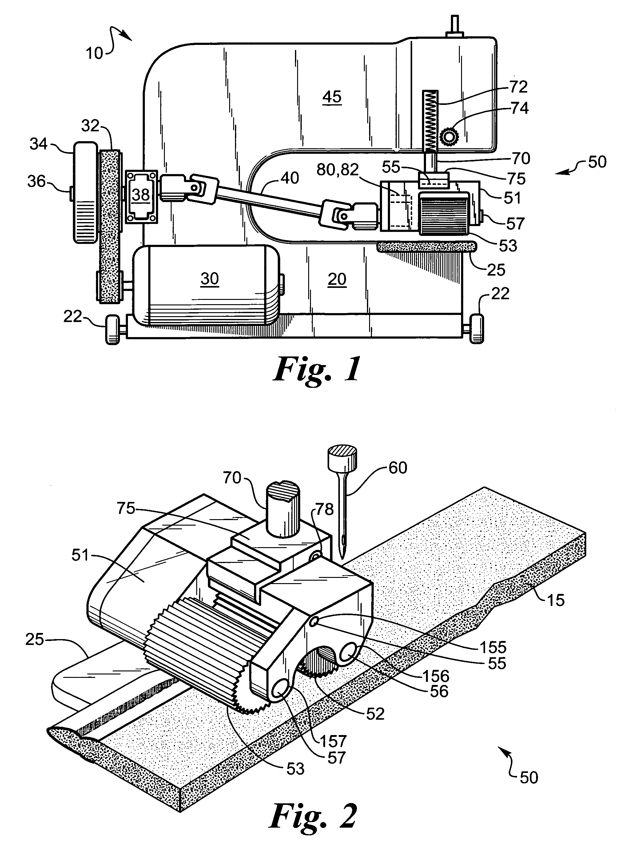
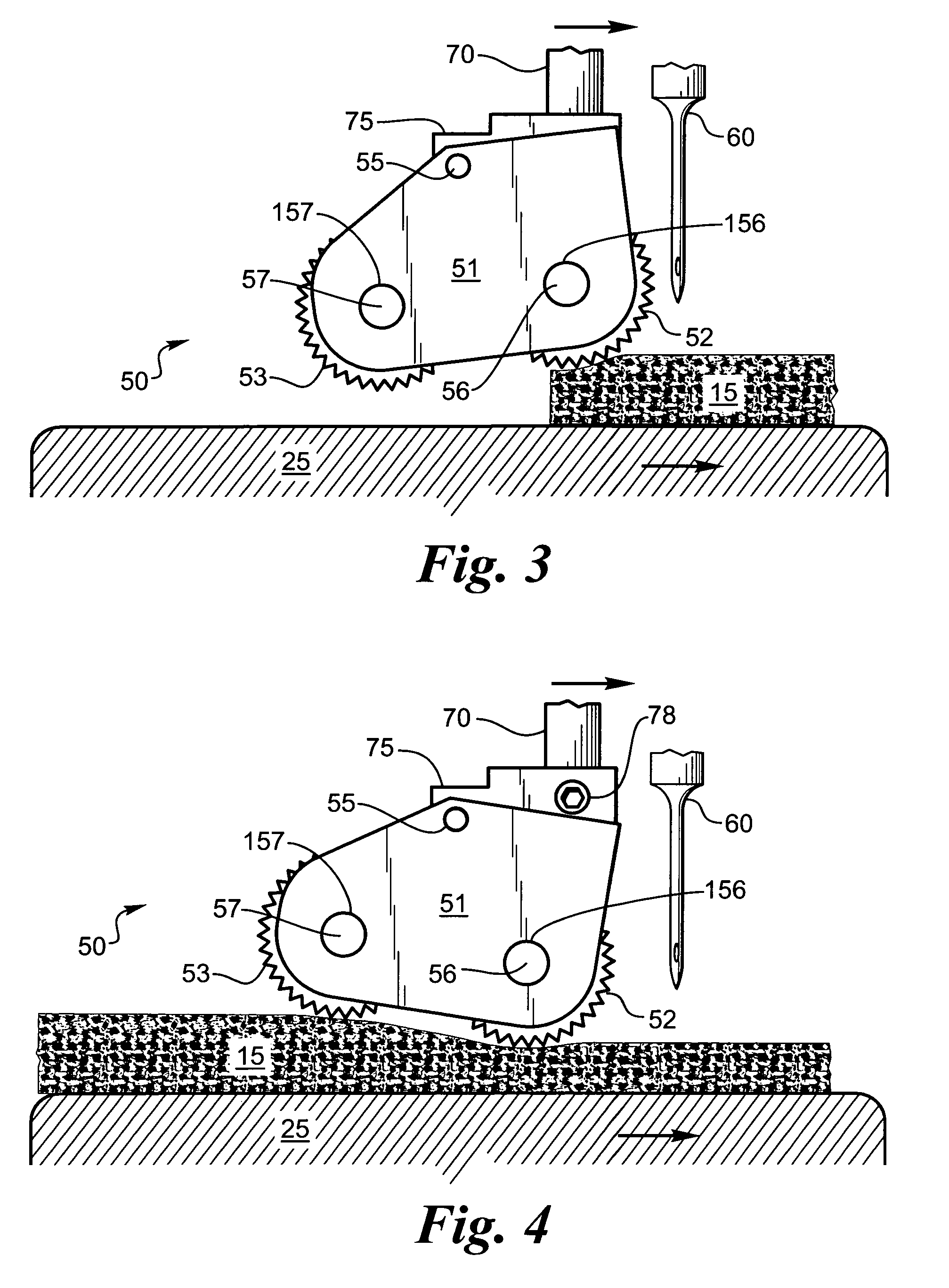
[0033]In laying carpet a sewing machine 10 is sometimes used to add a binding tape to the edge of the carpet 15. The sewing machine 10 can be on wheels 22 and run along the edge of the carpet 15 or the carpet 15 can be run through a stationary sewing machine 10. In either case the carpet 15 has to be fed through the sewing machine 10 with a firm grip on the carpet 15 to advance the carpet 15 with each stitch.

[0034]In general a sewing machine 10 having a frame 20 may optionally have wheels 22 for moving the sewing machine 10 along the edge of a carpet 15. The sewing machine 10 has an electric motor 30 for driving a belt 32, which rotates shaft 36 having a flywheel 34 thereon. Shaft 36 also drives a cam and a one-way clutch bearing mechanism shown generally as box 38, which then drives drive shaft 40 connected to pivoting twin feed roller 50. The a one-way clutch bearing mechanism box 38 also contains a means for allowing a shaft to slide therein to compensate for the up and down moti...


PUM


Abstract

A pivoting twin roller for feeding a material to a sewing machine is disclosed. The twin rollers grip the material with serrated rollers, which rotate at the same rate for uniformly moving the material relative the sewing machine. The twin rollers press down on the material with equal force due to the central pivot point, which improves the feed of the material. The pivoting twin rollers also allow for automatic feeding of material to the sewing machine. A spring loading on the housing for the pivoting twin rollers applies downward pressure on the material being sewn for a sure grip thereon. The downward pressure also insures that the rollers will press down with equal force on uneven height materials since the pivot adjusts the height of the rollers to the height of the materials and thus prevents floating which can lead to jamming of the sewing machine.

Description

BACKGROUND OF THE INVENTION[0001]1. Field of the Invention[0002]This invention relates to sewing machines and more particularly to a carpet sewing machine with twin feed rollers having a pivot point between the rollers to better feed the material to be sewn to the sewing machine.[0003]2. Description of the Related Art[0004]Twin roller feeds for material have been used in sewing machines. The twin rollers are synchronized to rotate together and both engage the material to be sewn, such as carpeting, at the same time. The rollers are fixed at the same height and both rollers travel up and down at the same rate. Problems arise when the material to be sewn is of uneven thickness since one roller will be pressing down on the material too hard and apply too much force on the material while the other roller is floating above the material providing little or no traction, thus causing bunching of the material between the rollers. This may cause an uneven feed resulting in jamming or uneven s...

Claims


Application Information

Patent Timeline
IPC IPC(8): D05B27/10
CPCD05B27/12D10B2503/04
Inventor ANDERSON, MARTIN L.
Owner NAT FLOORING EQUIP INC
Why Eureka
Try Eureka