Belt module with oblong pivot hole

a technology of oblong pivot holes and belt modules, which is applied in the direction of conveyors, transportation and packaging, etc., to achieve the effect of convenient maintenance and better cleaning

Active Publication Date: 2006-07-25
HABASIT AG
View PDF24 Cites 14 Cited by
  • Summary
  • Abstract
  • Description
  • Claims
  • Application Information

AI Technical Summary

Benefits of technology

[0006]The present invention meets the above-described need by providing an endless conveyor belt formed of plastic belt modules having pivot holes in their link ends that are disposed at an angle relative to the plane defined by the top surface of the belt module. In comparison with a completely round hole, the shape of the angled, oblong pivot holes do not reduce the thickness of the module between the pivot holes and the top surface of the module. Therefore the pivot holes of the present invention do not significantly weaken the module and can be extended lengthwise to provide a larger opening for cleaning.
[0009]In an assembled conveyor belt, adjacent belt modules align with each other such that the transverse holes in the adjacent link ends are angled in opposite directions. As a result, the pivot rod is captured by the respective holes in an overlapping area so that the pivot rod is confined to a portion of each of the elongate holes and is not free to move along the entire length of either of the holes. The cooperation of the adjacent angled holes prevents translatory motion of the pivot rod, and provides access to the transverse hole and to the pivot rod for cleaning. Accordingly, the present design provides for greater access to the inside of the transverse holes and to the pivot rods for better cleaning and easier maintenance. The enhancement is provided without introducing any undesirable translatory motion or “play” in the belt.

Problems solved by technology

As a result, the pivot rod is captured by the respective holes in an overlapping area so that the pivot rod is confined to a portion of each of the elongate holes and is not free to move along the entire length of either of the holes.

Method used


Image

  • Belt module with oblong pivot hole
  • Belt module with oblong pivot hole
  • Belt module with oblong pivot hole

Examples


Embodiment Construction

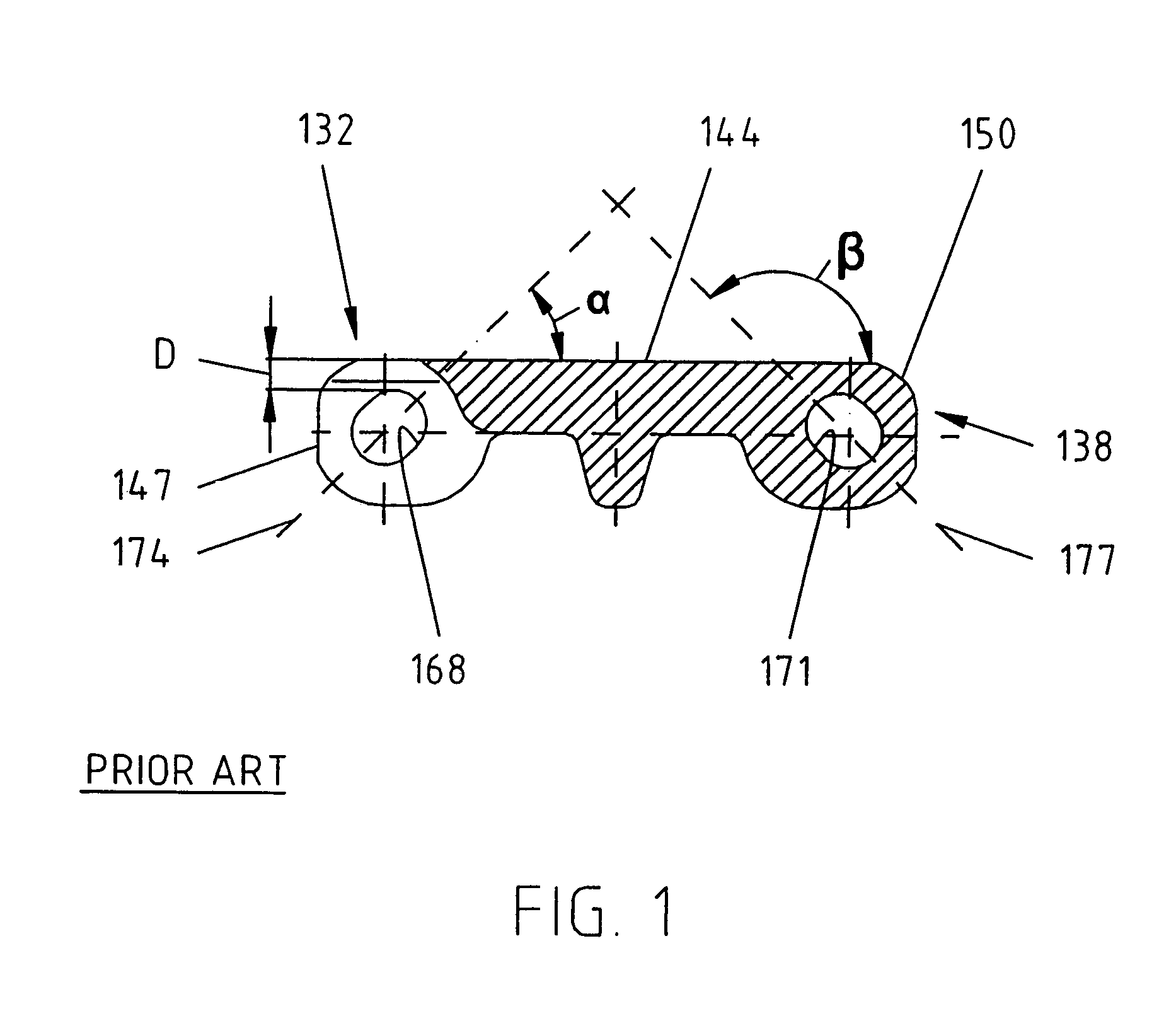
[0016]In FIG. 1, a prior art module is shown, the curved portion 147 of the link end 132 is shown at one end of the figure and at the opposite end of the figure the curved surface 150 at the end of the second link end 138 is shown. Also, first and second elongate transverse holes 168, 171 are shown. The transverse holes 168, 171 have longitudinal axes 174 and 177 respectively. The transverse holes 168, 171 are preferably elongate and oval-shaped. The transverse hole 168 is angled at an angle α which is 10° to 80° relative to the horizontal axis defined by top surface 144. The preferred embodiment provides for an angle α of approximately 45°. The transverse hole 171 on the opposite end of the module is rotated by approximately 90° such that it is disposed at an angle β approximately 100° to 170° to the top surface 144. The preferred embodiment for the second hole 171 is an angle β of approximately 135°. As shown, the shape of holes 168 and 171 being elongate and extending at a 45° an...


PUM


Abstract

A modular conveyor belt formed of rows of belt modules pivotally interlinked by transverse pivot rods. The modules include a top, product conveying surface and a bottom, sprocket-driven surface. The belt modules have a plurality of first link ends disposed in the direction of travel of the conveyor belt and a plurality of second link ends disposed in the opposite direction. Transverse holes in the link ends are aligned to accommodate a pivot rod. When the link ends of the consecutive rows of side by side modules are intercalated, the pivot rod serves as a hinge pin in a hinged joint between consecutive interlinked rows. The transverse holes are disposed at an angle relative to the top surface of the belt module such that when the belt modules are connected to form a belt the transverse holes in adjacent link ends are disposed at opposite angles.

Description

FIELD OF INVENTION[0001]This invention relates to conveyor belts and, more particularly, to modular plastic conveyor belts formed of rows of plastic belt modules pivotally interlinked by transverse pivot rods.BACKGROUND OF THE INVENTION[0002]Because they are lightweight, do not corrode, and are easy to clean, unlike metal conveyor belts, plastic conveyor belts are used widely, especially in conveying food products. Modular plastic conveyor belts are made up of molded plastic modular links, or belt modules, that can be arranged side by side in rows of selectable width. A series of spaced apart link ends extending from each side of the modules include aligned apertures or holes to accommodate a pivot rod. The link ends along one end of a row of modules are interconnected with the link ends of an adjacent row. A pivot rod journaled in the aligned apertures of the side-by-side and end-to-end connected modules forms a hinge between adjacent rows. Rows of belt modules are connected togeth...

Claims


Application Information

Patent Timeline
Patent Type & Authority Patents(United States)
IPC IPC(8): B65G17/06
CPCB65G17/08
Inventor GULDENFELS, DIETERVETTER, MARKUS BERNHARD
Owner HABASIT AG
Why Eureka
Try Eureka