Luminal anastomotic device

a technology of anastomosis and anastomosis, which is applied in the direction of surgical staples, paper/cardboard containers, manufacturing tools, etc., can solve the problems of not providing an anvil and unable to provide a continuous stapler lin

Inactive Publication Date: 2006-07-25
VRESH SUSAN E +3
View PDF15 Cites 1692 Cited by
  • Summary
  • Abstract
  • Description
  • Claims
  • Application Information

AI Technical Summary

Benefits of technology

[0021]One advantage of the present invention is a minimally invasive surgical stapler that will assist in stapler placement because the diameter of the stapler (i.e. the largest diameter portion, specifically the head and anvil of the stapler) is smaller during insertion and retraction than at firing.
[0022]Another advantage of the present invention is having a closed loop EEA stapler with the trimming knife formed by individual knife segments. This feature of the present invention may be utilized for firing the knife segments individually, or in a given sequence, or simultaneously (as utilized in the illustrated embodiments of the present invention.
[0023]Another feature of the present invention is the accommodation of multiple anvil and multiple head controls in a surgical stapler. One present illustrated embodiments provide separate controls for expansion / retraction of the anvil and for axial movement of the anvil. This illustrated embodiment further provides independent control for expansion / retraction of the head and for firing of the knife blade and staples. This system of multiple independent control may be modified to perform a variety of separate control features for the anvil and head portions of an EEA stapler.
[0024]Another feature of the present invention is the provision of an EEA stapler with a staple and knife firing mechanism that accommodates relative motion of the head portion containing the staples and the firing mechanism.
[0025]Another feature of the present invention is the provision of an alignment mechanism that aligns and locks the anvil and head portion together prior to the firing of the staples or the knife.
[0026]Another feature of the present invention is the provision of a closed loop surgical stapler for end to end anastomosis in which the stapler extends around the outside of the lumen portions being anastomised.

Problems solved by technology

The anvil is not detachable from the stapler and thus cannot provide a continuous stapler line, but rather applies a broken, discontinuous line to “tack” the tissue in a circular line.
This patent also does not provide an anvil which can be placed remotely within the body for subsequent attachment to a stapler head.
The retractable anvil EEA's discussed above do not address the fundamental problem of the constrictive point formed after luminal anastomosis.

Method used


Image

  • Luminal anastomotic device
  • Luminal anastomotic device
  • Luminal anastomotic device

Examples


Embodiment Construction

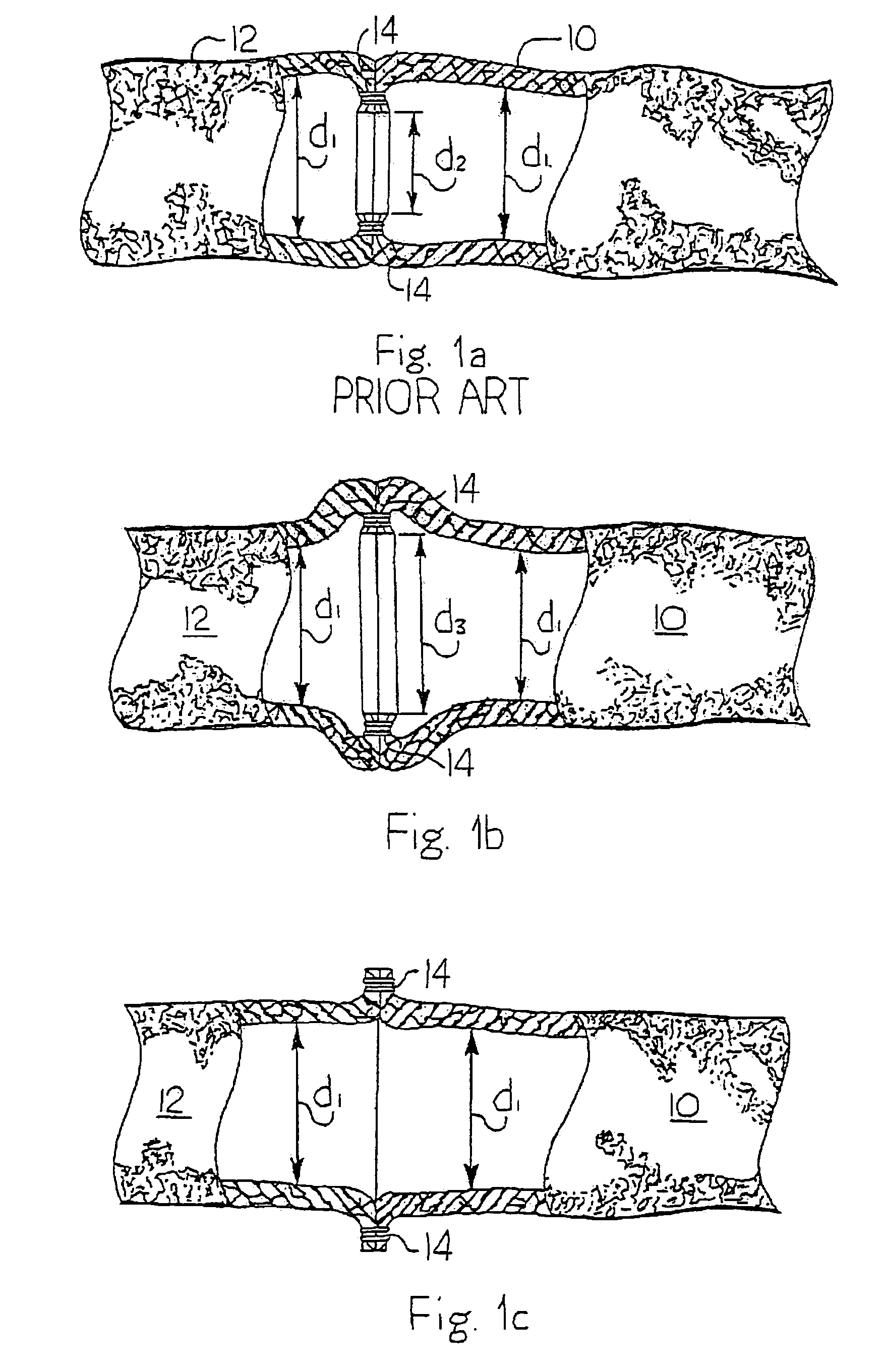
[0059]The objects and advantages of the present invention can be best clarified in reviewing the surgical results illustrated in FIGS. 1a, 1b and 1c with the prior art surgical staplers (FIG. 1a) and various embodiments of surgical staplers (FIGS. 1b and 1c) of the present invention, respectively. FIG. 1a illustrates lumen sections 10 and 12 anastomized with a conventional intraluminal anastomotic stapler (i.e. an EEA). The first lumen section 10 and second lumen section 12 will have a nominal diameter d.sub.1. With existing end to end anastomotic staplers, the anastomosis site, sometimes referred to as an anastomosis ring, formed by an array of staples 14 will have a smaller diameter d.sub.2 than the nominal luminal diameter d.sub.1. In addition to the constrictive point formed by the smaller diameter d.sub.2, with the existence of (1) the array of staples 14, (2) the additional tissue formed by the coupled lumen sections at the anastomosis site, and (3) the scar tissue forming aro...


PUM

PropertyMeasurementUnit
diameteraaaaaaaaaa
timeaaaaaaaaaa
inner diameteraaaaaaaaaa

Abstract

An end to end anastomotic stapling device connects two lumen sections avoiding constriction at the anastomotic ring. An intraluminal end to end anastomotic stapler includes an expanding head and anvil designed to fire an anastomotic ring having an inner diameter at least equal to the nominal inner diameter of the remaining lumen sections. An extraluminal end to end lumen stapler is described attaching the lumen sections with an exterior flange type connection having anastomotic rings with a diameter larger than the inner diameter of the lumen sections whereby the anastomotic site has a diameter at least as great as the adjacent lumen sections.

Description

CROSS-REFERENCE TO RELATED APPLICATION[0001]This application is a continuation of and claims the benefit of U.S. patent application Ser. No. 10 / 114,421, filed on Apr. 2, 2002 and entitled “Luminal Anastomotic Device and Method”, now U.S. Pat. No. 6,769,590 which claimed the benefit of Provisional Patent Application Ser. No. 60 / 280,785 entitled, “Luminal Anastomotic Device and Method” filed Apr. 2, 2001. Both applications are incorporated herein by reference in their entirety.BACKGROUND OF THE INVENTION[0002]1. Field of the Invention[0003]The present invention relates to surgical anastomotic stapling devices. More particularly, the present invention relates to end to end anastomotic surgical staplers avoiding minimal constrictive area at the anastomosis site.[0004]2. Background Information[0005]Surgical staplers have been developed to assist and improve a wide variety of surgical procedures. Surgical staplers provide precision in the placement of staples as well as decrease the time ...

Claims


Application Information

Patent Timeline
Patent Type & Authority Patents(United States)
IPC IPC(8): B31B1/00A61B17/04A61B17/11A61B17/115
CPCA61B17/1114A61B17/115A61B2017/1132A61B17/1155A61B17/1152A61B2017/00349
Inventor VRESH, SUSAN E.SHIDELER, BLYNN L.SHIDELER, KRISANNEVRESH, KEVIN S.
Owner VRESH SUSAN E
Why Eureka
Try Eureka