Methods and apparatus for disinfecting and sterilizing fluid using ultraviolet radiation

a technology of disinfecting fluid and ultraviolet radiation, which is applied in the direction of instruments, discharge tubes luminescnet screens, water/sewage treatment by oxidation, etc. it can solve the problems of affecting the performance of lamps, lamps are easy to break, and the fragile nature of lamps cannot be handled in harsh environments, so as to speed up the killing effect of ultraviolet light and improve the sterilization effect of the disinfecting aspect of the apparatus

Inactive Publication Date: 2006-07-25
HOLLANDER BRAD C
View PDF62 Cites 73 Cited by
  • Summary
  • Abstract
  • Description
  • Claims
  • Application Information

AI Technical Summary

Benefits of technology

[0006]According to the invention, an apparatus for sterilizing or disinfecting fluids, which comprises a fluid conduit, an ultraviolet light source, which is at least partially within the fluid conduit, and an air drive unit coupled to the fluid conduit. The ultraviolet light source generates an ultraviolet light, which kills microorganisms in the fluid, thus sterilizing or disinfecting the fluid. The air dive unit creates air bubbles in the fluid, such as for fish tanks, fish hatchery ponds, or the like. As one skilled in the art will appreciate, the air bubbles also can help speed-up the killing effect of the ultraviolet light, thus making the sterilizing of disinfecting aspect of the apparatus more effective.

Problems solved by technology

While ultraviolet light sources have been used for some time for sterilization purposes, a problem with the ultraviolet light sources currently known in the art is that they are fragile and typically cannot handle the harsh environments in which they must be used.
For example, because the prior art ultraviolet light sources are made of soft glass or quartz, the lamps tend to break easily.
In addition, because of the adhesive nature of the soft glass or quartz casing, residue and other impurities tend to build up on the lamps over time, affecting the performance of the lamp.
Finally, the prior art ultraviolet light sources have a tendency to be expensive and difficult to maintain.

Method used


Image

  • Methods and apparatus for disinfecting and sterilizing fluid using ultraviolet radiation
  • Methods and apparatus for disinfecting and sterilizing fluid using ultraviolet radiation
  • Methods and apparatus for disinfecting and sterilizing fluid using ultraviolet radiation

Examples


Embodiment Construction

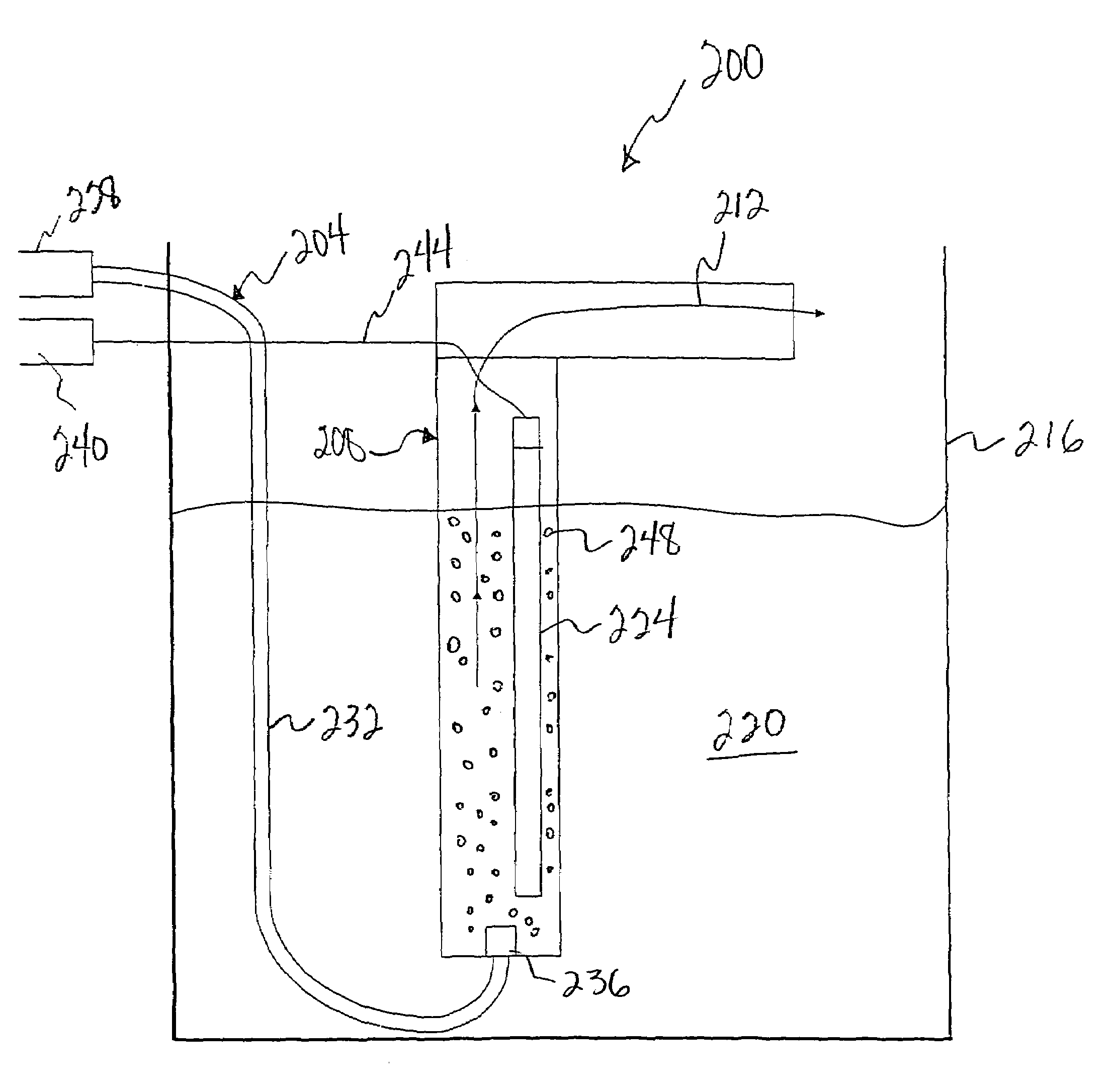
[0020]The present invention relates generally to methods and apparatus for disinfecting and sterilizing fluids and the surfaces of containers, pipes, ducts and other suitable devices with which the fluids contact. More particularly, the present invention relates to a novel embodiment of an ultraviolet light source, which performs the disinfecting and sterilizing processes using a fluid conduit.

[0021]In accordance with the present invention, the term fluid means a continuous, amorphous substance whose molecules move freely past one another and that has the tendency to assume the shape of its container; that is, a fluid can be a liquid or gas, including air. In addition, the term may refer to plasma type materials.

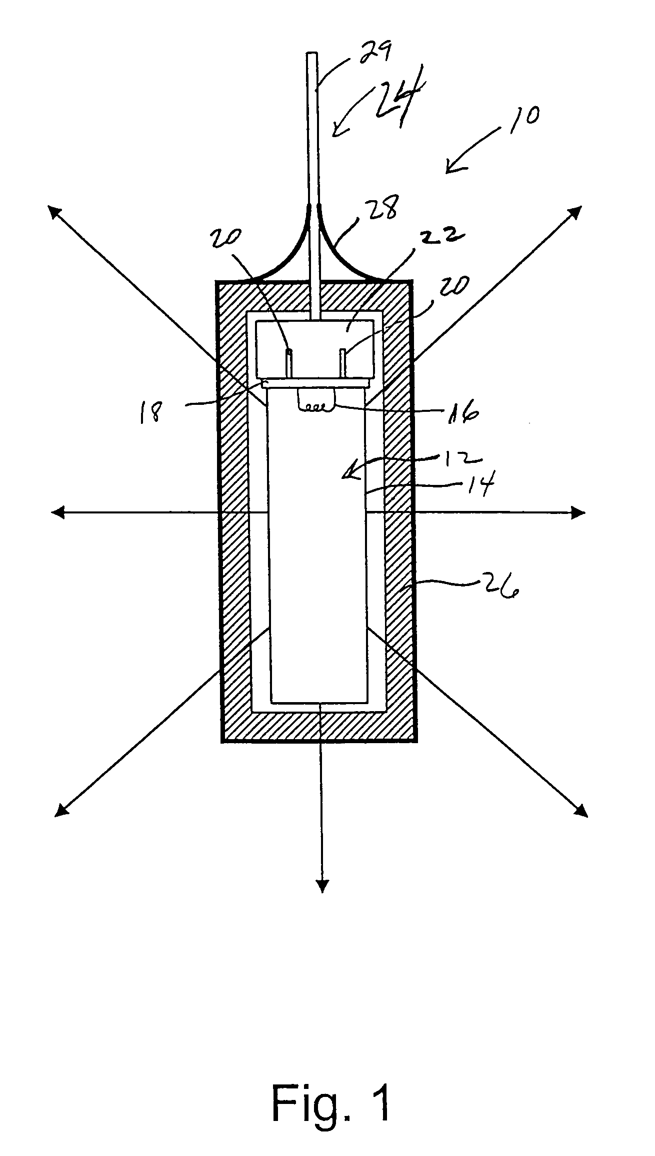
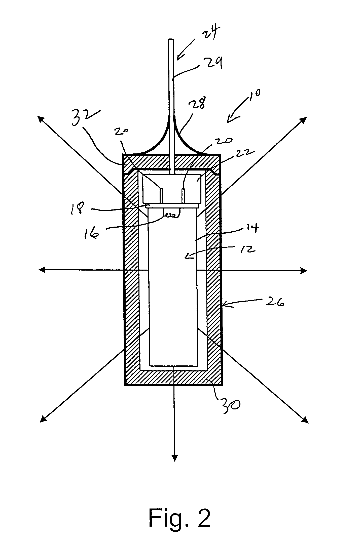
[0022]Referring now to FIG. 1, an apparatus 10 for disinfecting and / or sterilizing a fluid is shown. In accordance with the illustrated embodiment, Apparatus10 preferably comprises an ultraviolet lamp or light bulb 12, a ballast 22, a power source 24, and a protective coatin...


PUM

PropertyMeasurementUnit
solar poweraaaaaaaaaa
poweraaaaaaaaaa
plasmaaaaaaaaaaa

Abstract

An apparatus for sterilizing or disinfecting fluids, which comprises a fluid conduit, an ultraviolet light source, which is at least partially within the fluid conduit, and an air drive unit coupled to the fluid conduit. The ultraviolet light source generates an ultraviolet light, which kills microorganisms in the fluid, thus sterilizing or disinfecting the fluid. The air dive unit creates air bubbles in the fluid, such as for fish tanks, fish hatchery ponds, or the like. In accordance with one embodiment of the present invention, the ultraviolet light source comprises an ultraviolet light bulb being surrounded by a protective sleeve. The protective sleeve preferably comprises a UV transmissive material, which may comprise a fluoropolymer material, such as PTFE, FEP, PFA, AF and Tefzel ETFE.

Description

CROSS-REFERENCES TO RELATED APPLICATION[0001]This patent application claims the benefit of U.S. Provisional Patent Application Ser. No. 60 / 144,638, filed Jul. 20, 1999, the entirely of which is incorporated herein by reference for all purposes.BACKGROUND OF THE INVENTION[0002]The present invention relates generally to methods and apparatus for disinfecting and sterilizing fluids using an ultraviolet light source, and more particularly to a novel pump which can be used in a wide variety of harsh environments to pump fluid and kill micro organisms living in the fluids.[0003]The use of ultraviolet light sources for sterilizing and disinfecting fluids is well-known in the art. A typical ultraviolet light source has two primary parts, the tube and the base. The tube usually comprises a soft glass or quartz casing which holds a vaporizable material, such as mercury, and a starting gas and / or stabilizing gas, such as argon, neon, zeon or the like. The tube also includes one or more electro...

Claims


Application Information

Patent Timeline
Patent Type & Authority Patents(United States)
IPC IPC(8): C02F1/32
CPCA61L2/10A61L9/20C02F1/325C02F2209/40C02F2103/20C02F2201/004C02F2201/3225C02F1/74Y02W10/37
Inventor HOLLANDER, BRAD C.
Owner HOLLANDER BRAD C
Why Eureka
Try Eureka