Kinetic energy rod warhead with isotropic firing of the projectiles

a technology of kinetic energy rods and projectiles, applied in the field of improvements, can solve the problems of heavy casualties and ineffective destruction of targets

Inactive Publication Date: 2006-05-09
OL SECURITY LIABILITY CO
View PDF24 Cites 24 Cited by
  • Summary
  • Abstract
  • Description
  • Claims
  • Application Information

AI Technical Summary

Benefits of technology

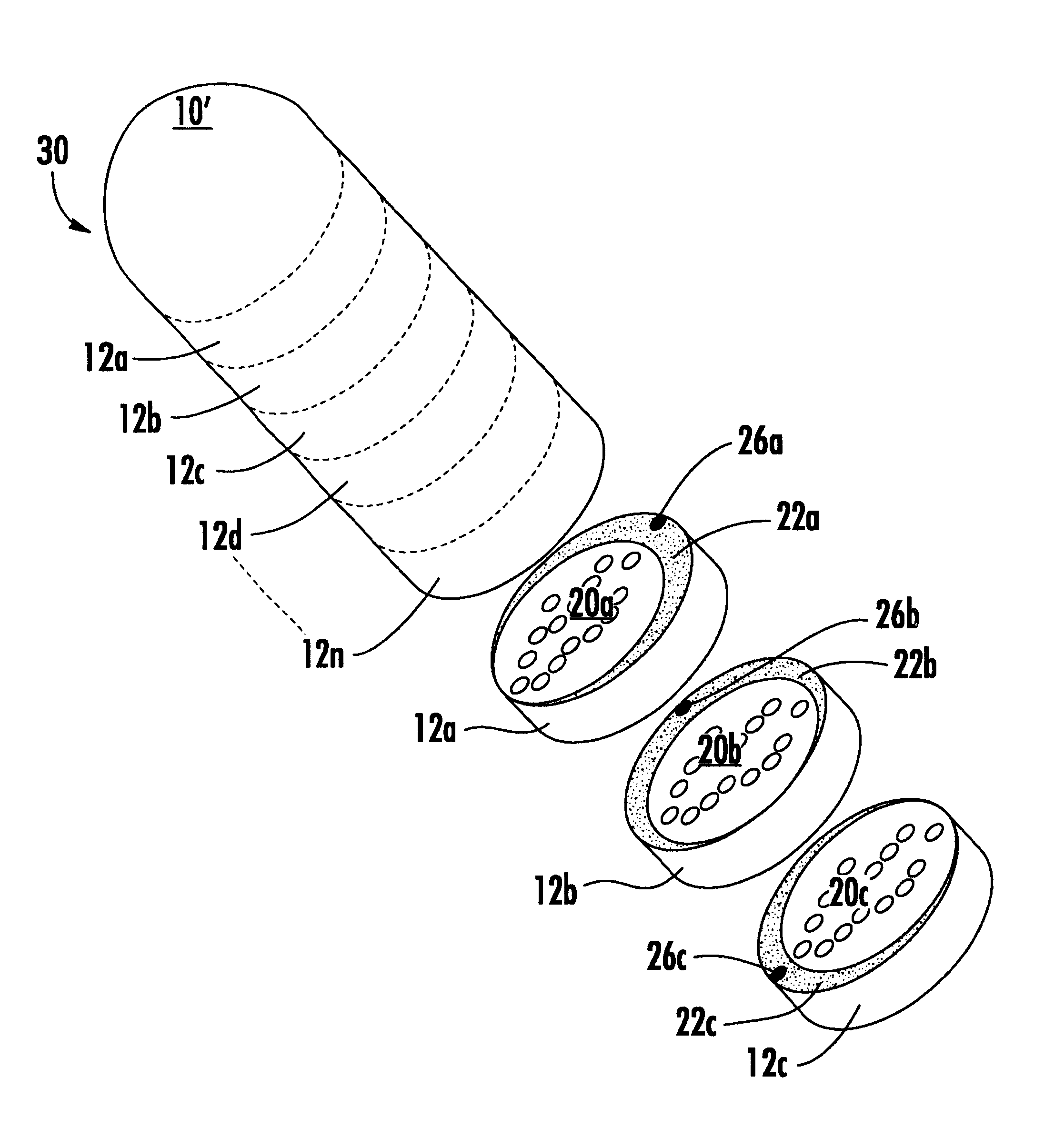
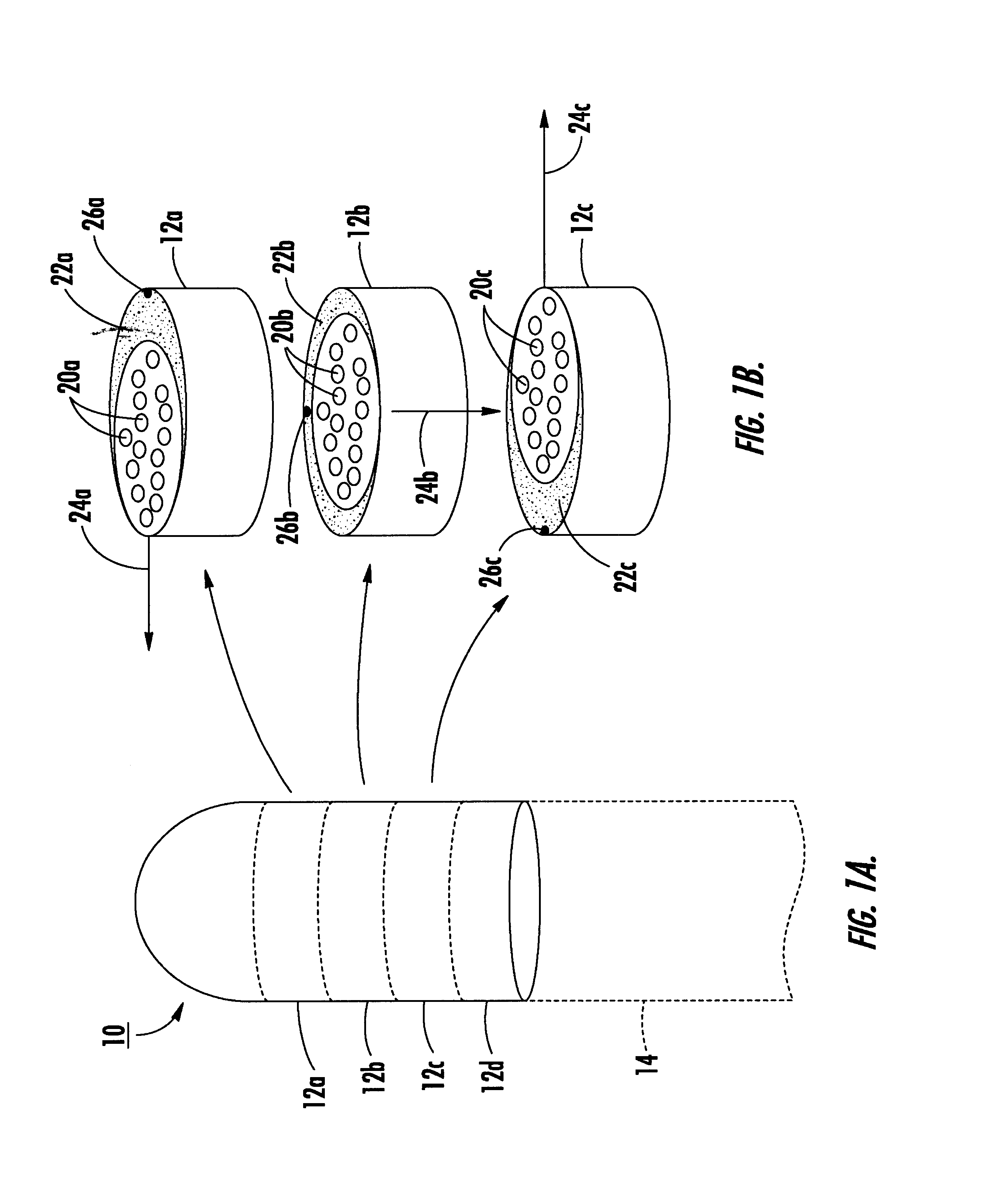
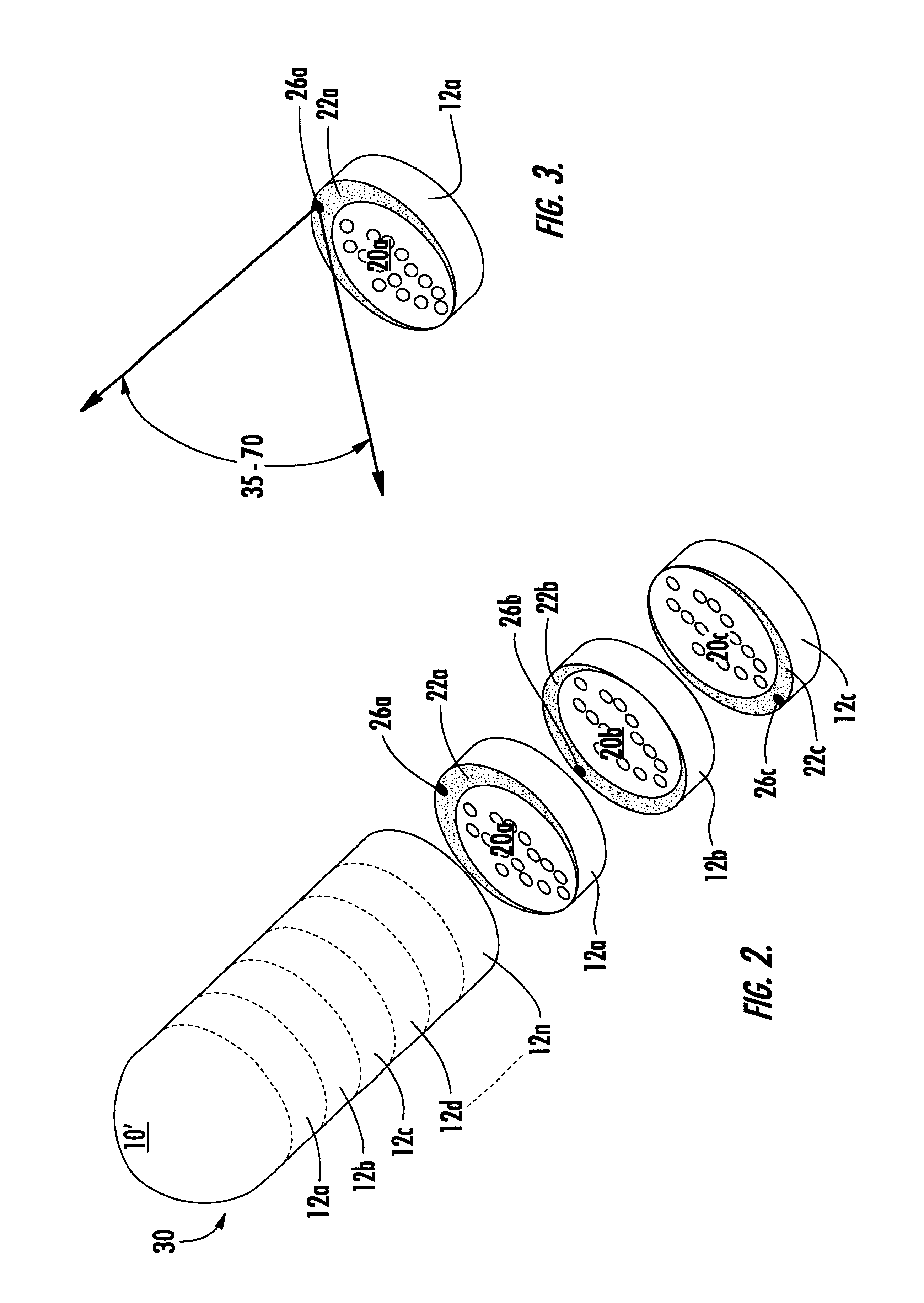
[0010]In this invention, the kinetic energy rod warhead is divided into housings or sections each enclosing in a number of projectiles and an explosive charge partially surrounding the projectiles and defining a firing direction. The firing direction of each kinetic energy rod warhead section is designed to be different so that the projectiles can be isotropically deployed. In this way, without the need for a center core, the projectiles can still be deployed isotropically but without the complexity or additional mass of a large center core explosive.

Problems solved by technology

Moreover, biological warfare bomblets and chemical warfare submunition payloads are carried by some threats and one or more of these bomblets or chemical submunition payloads can survive and cause heavy casualties even if the “hit-to-kill” vehicle accurately strikes the target.
The fragments, however, are not always effective at destroying the target and, again, biological bomblets and / or chemical submunition payloads may survive and cause heavy casualties.

Method used


Image

  • Kinetic energy rod warhead with isotropic firing of the projectiles
  • Kinetic energy rod warhead with isotropic firing of the projectiles
  • Kinetic energy rod warhead with isotropic firing of the projectiles

Examples


Embodiment Construction

[0030]Kinetic energy rod warhead 10, FIG. 1A includes n sections 12A-12D typically positioned and deployed in space via missile 14 shown in phantom. Three exemplary kinetic energy rod warhead sections 12a-12c are shown in FIG. 1B each enclosing a plurality of lengthy titanium, tantalum, or tungsten projectiles 20 and explosive charge 22 defining different primary firing directions 24. In this example, if there are three kinetic energy rod warhead sections, they define firing directions 120° apart. Detonators 26 initiate the explosive charges typically all at the same time. One kinetic energy rod warhead 10 is in position to destroy a missile, aircraft, re-entry vehicle, or other target, sections 12a-12c are deployed as shown in FIG. 1B and detonators 26a-26c actuated. Then, the projectiles 20a of kinetic energy rod warhead section 12a are urged in firing direction 24a by explosive 22a, projectiles 20b of kinetic energy rod warhead section 12b are urged in firing direction 24b by exp...


PUM


Abstract

A kinetic energy rod warhead including a plurality of sections each enclosing a plurality of projectile and an explosive charge partially surrounding the projectiles defining a primary projectile firing direction. The firing direction of each section is different for isotropically deploying the projectiles.

Description

PRIORITY CLAIM[0001]This application claims priority of Provisional Application Ser. No. 60 / 406,828 filed Aug. 29, 2002.FIELD OF THE INVENTION[0002]This invention relates to improvements in kinetic energy rod warheads.BACKGROUND OF THE INVENTION[0003]Destroying missiles, aircraft, re-entry vehicles and other targets falls into three primary classifications: “hit-to-kill” vehicles, blast fragmentation warheads, and kinetic energy rod warheads.[0004]“Hit-to-kill” vehicles are typically launched into a position proximate a re-entry vehicle or other target via a missile such as the Patriot, THAAD or PAC3 missile. The kill vehicle is navigatable and designed to strike the re-entry vehicle to render it inoperable. Countermeasures, however, can be used to avoid the “hit-to-kill” vehicle. Moreover, biological warfare bomblets and chemical warfare submunition payloads are carried by some threats and one or more of these bomblets or chemical submunition payloads can survive and cause heavy ca...

Claims


Application Information

Patent Timeline
Patent Type & Authority Patents(United States)
IPC IPC(8): F42B12/56F41H11/04F41H13/00F42B12/20F42B12/60F42B12/64F42C19/095
CPCF42B12/64F42B12/60
Inventor LLOYD, RICHARD M.
Owner OL SECURITY LIABILITY CO
Why Eureka
Try Eureka