Method for processing a golf club head with cup shaped face component

a golf club head and component technology, applied in the field of manufacturing the face component can solve the problems of increasing the energy transfer problem, reducing reducing the efficiency of the golf club head, so as to improve the compliance of the striking face, reduce the energy loss, and improve the effect of the restitution coefficien

Active Publication Date: 2006-08-01
TOPGOLF CALLAWAY BRANDS CORP
View PDF72 Cites 82 Cited by
  • Summary
  • Abstract
  • Description
  • Claims
  • Application Information

AI Technical Summary

Benefits of technology

[0013]The present invention is a method for producing a golf club head with a two-piece face component and a thin walled return portion flange between the striking face and the aft-body. The face component includes a formed or forged striking face insert and a cast face cup. This face component's thin-walled flange allows for greater compliance of the striking face with a golf ball during impact. A more compliant striking face provides for lower energy loss and a higher coefficient of restitution. In addition, the reduced weight of this two-piece face component enables additional weight to be strategically distributed to other areas of the club head to further enhance the playing characteristics of the golf club.

Problems solved by technology

Most of the energy is transferred from the head to the golf ball, however, some energy is lost as a result of the collision.
However, this leads to greater deformations in the golf ball, and thus increases in the energy transfer problem.
The process of forging the face component, however, has several limitations in terms of wall thicknesses that can be achieved around the flange.
It is not possible to forge face components with a very thin (less than 0.050 inch thickness) flange or a transition region between the striking face and the flange.
These design considerations lead to very short tool life in forging and thus increase the cost of making such face component shapes.
Although the prior art has disclosed many variations of multiple material club heads, the prior art has failed to provide a multiple material club head with a high coefficient of restitution at a lower production cost.

Method used


Image

  • Method for processing a golf club head with cup shaped face component
  • Method for processing a golf club head with cup shaped face component
  • Method for processing a golf club head with cup shaped face component

Examples


Embodiment Construction

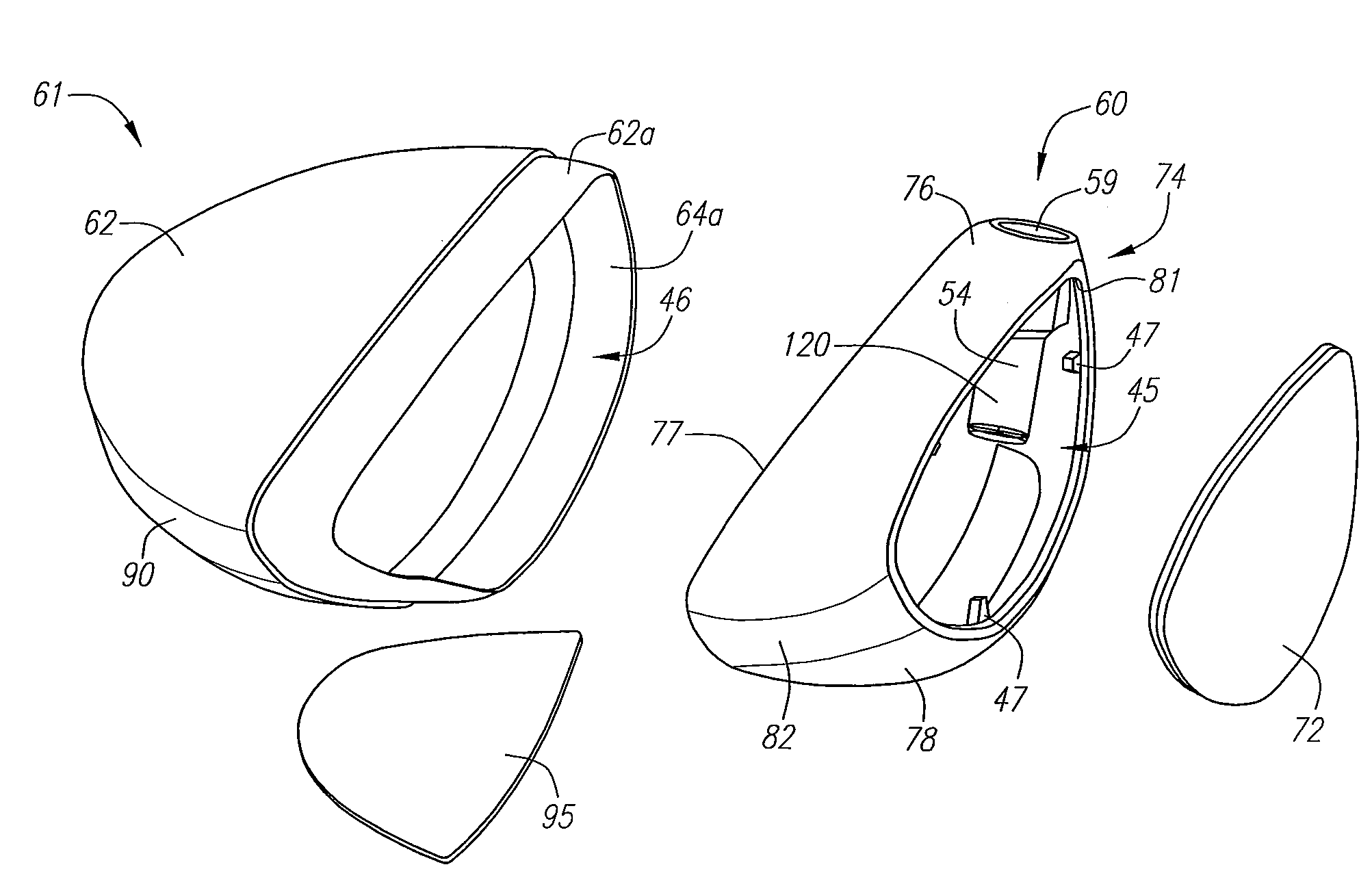
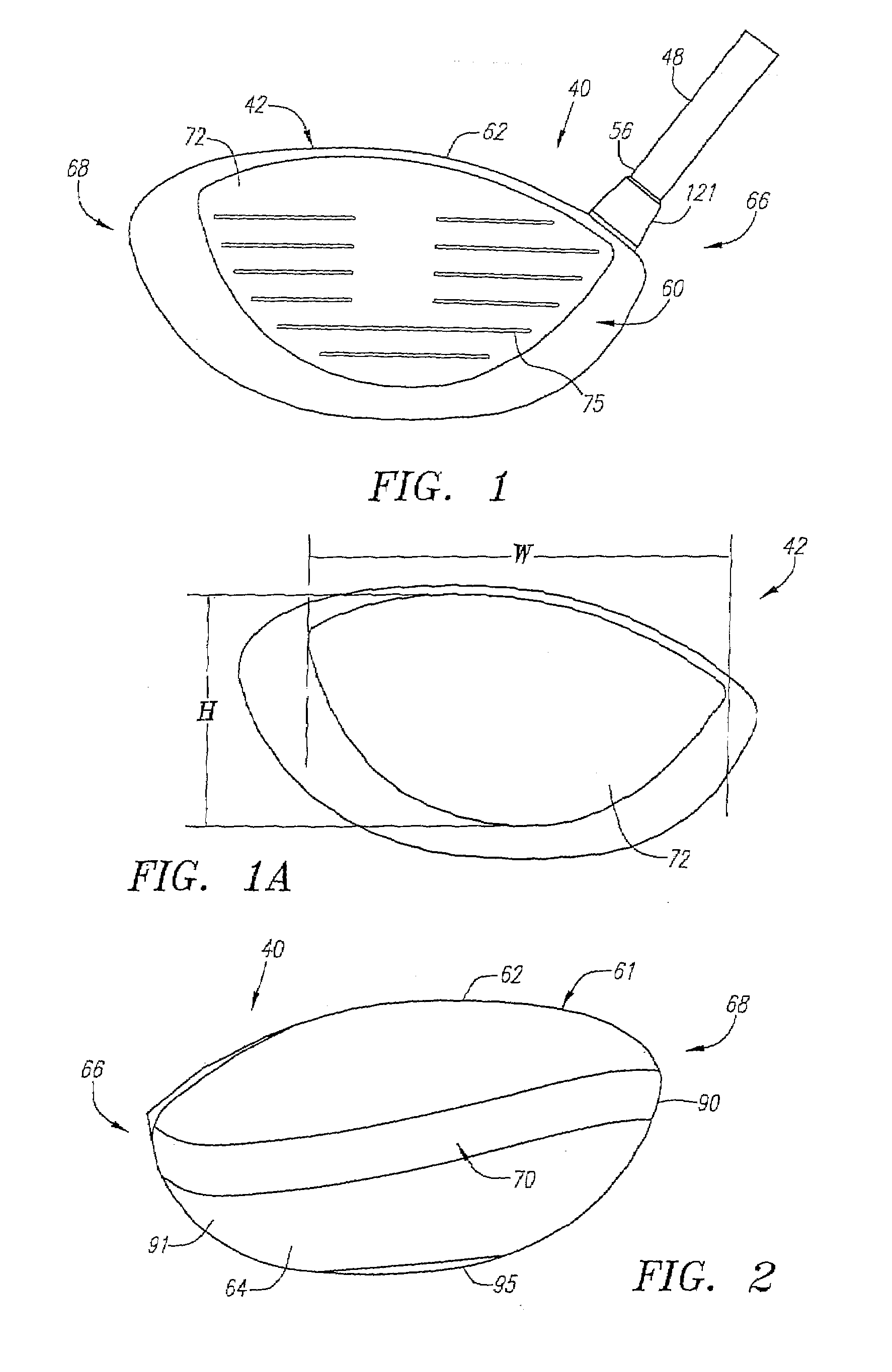
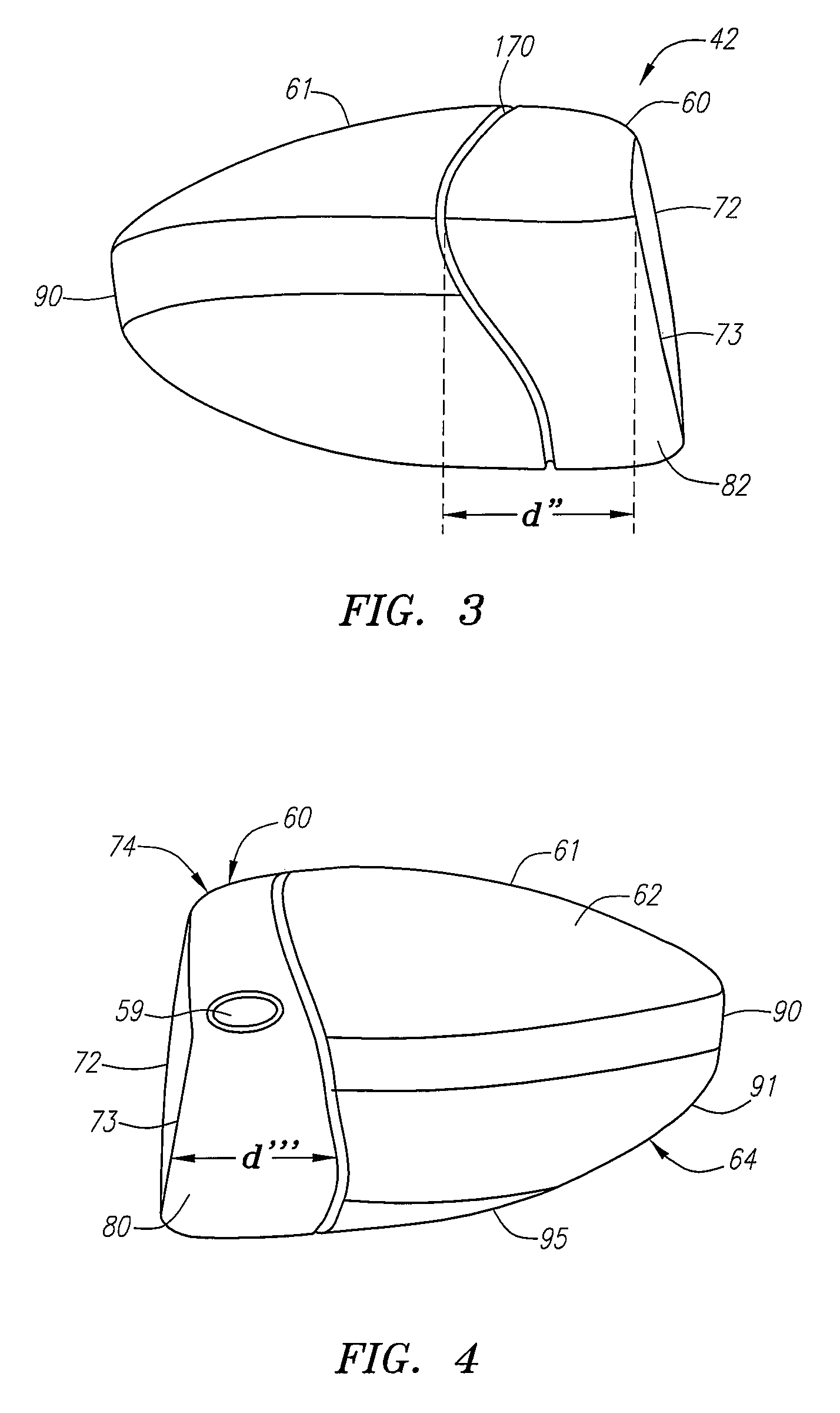
[0034]The present invention is directed at a method for producing a golf club head with a two-piece face component that includes a striking plate insert attached to a cast face cup. The cast face cup has a return portion with a thin-walled flange and transition zone, which allow for greater compliance of the striking face during impact with a golf ball. The compliant striking face provides the golf club head with a high coefficient of restitution thereby enabling a golf ball hit with the golf club head of the present invention to travel a greater distance. The coefficient of restitution (also referred to herein as “COR”) is determined by the following equation:

[0035]e=v2-v1U1-U2

[0036]wherein U1 is the club head velocity prior to impact; U2 is the golf ball velocity prior to impact which is zero; v1 is the club head velocity just after separation of the golf ball from the face of the club head; v2 is the golf ball velocity just after separation of the golf ball from the face of the c...


PUM

PropertyMeasurementUnit
thicknessaaaaaaaaaa
thicknessaaaaaaaaaa
thicknessaaaaaaaaaa

Abstract

A method for producing a golf club head (42) with a two-piece face component (60) and an aft-body (61) is disclosed herein. The face component (60) includes a formed or forged striking face insert (72) and a cast face cup (74) with a front face (81) and a return portion (77) and separately forming the striking face insert (72). The striking face insert (72) is then pressed or swaged into an opening in the front face (81) of the cast face cup (74) while at the same time the cast face cup (74) is coined. The striking face insert (72) is then welded to the face cup (74) on the interior surface of the face component (60). The assembled face component (60) is then attached to the aft-body (61).

Description

CROSS REFERENCE TO RELATED APPLICATIONS[0001]Not ApplicableFEDERAL RESEARCH STATEMENT[0002][Not applicable]BACKGROUND OF INVENTION[0003]1. Field of the Invention[0004]The present invention relates to a method for manufacturing the face component of a golf club head. More specifically, the present invention relates to a method for manufacturing a golf club head composed of a two-piece face component, including a cast return section and formed face insert.[0005]2. Description of the Related Art[0006]When a golf club head strikes a golf ball, large impacts are produced that load the club head face and the golf ball. Most of the energy is transferred from the head to the golf ball, however, some energy is lost as a result of the collision. The golf ball is typically composed of polymer cover materials (such as ionomers) surrounding a rubber-like core. These softer polymer materials having damping (loss) properties that are strain and strain rate dependent which are on the order of 10–10...

Claims


Application Information

Patent Timeline
Patent Type & Authority Patents(United States)
IPC IPC(8): B21B1/46B23P21/00B21B1/00A63B53/04B21D39/03B29D99/00
CPCA63B53/0466A63B2053/0416A63B2209/00A63B2053/0433Y10T29/49988A63B2053/0437Y10T29/49904Y10T29/49989Y10T29/49826A63B2053/0408A63B53/0408A63B53/0416A63B53/0437A63B53/0433
Inventor DESHMUKH, UDAY V.REYES, HERBERT
Owner TOPGOLF CALLAWAY BRANDS CORP
Why Eureka
Try Eureka