Pressurizer for a rocket engine

Inactive Publication Date: 2006-08-01
KNIGHT ANDREW F
View PDF22 Cites 19 Cited by
  • Summary
  • Abstract
  • Description
  • Claims
  • Application Information

AI Technical Summary

Benefits of technology

[0015]In another preferred embodiment, the present invention provides for an impulse reaction engine system, comprising: an impulse reaction engine; a propellant tank configured to contain propellant at a low pressure; a gas generator configured to generate pressurant at a high pressure from liquid propellants; and a pressurizer configured to transfer propellant from said propellant tank at said low pressure to said impulse reaction engine at said high pressure in a substantially continuous flow, said pressurizer comprising: at least two storage tanks, wherein, for each storage tank, said pressurizer further comprises: a propellant entrance valve associated with said storage tank and connected between said storage tank and said propellant tank; a propellant exit valve associated with said storage tank and connected between said storage tank and said impulse reaction engine; a pressurant entrance valve associated with said storage tank and connected between said storage tank and said gas generator; and a pressurant exit valve connected to and associated with said storage tank, wherein each of said storage tanks is configured to be filled with said fluid under said low pressure when its associated propellant entrance and pressurant exit valves are open and its associated propellant exit and pressurant entrance valves are closed, and to be drained of said fluid under said high pressure by the force of said pressurant when its associated propellant entrance and pressurant exit valves are closed and its associated propellant exit and pressurant entrance valves are open, wherein, for each storage tank, its associated valves are configured to be opened and closed in a cycle to sequentially fill and drain their associated storage tank of said fluid, said cycle having a cycle time, wherein said cycles of said associated valves of said storage tanks are out of phase with each other such that at some time in which one storage tank is being filled with said fluid, at least one other storage tank is being drained of said fluid, and wherein said cycle time for each storage tank is between 1 and 500 milliseconds. The cycle time may be between 1 and 100 milliseconds.
[0016]In a preferred aspect, said pressurizer may further comprise a differential piston inside each storage tank. In another aspect, said pressurizer may further comprise a gas generator pump configured to pump propellant from a high-pressure outlet of said pressurizer to said gas generator.
[0017]In another preferred aspect, said associated pressurant exit valve for each storage tank may comprise at least one flow hole and a movable valving member configured to restrict flow through said flow hole, wherein each storage tank comprises a movable partition configured to substantially separate said propellant from said pressurant during filling and draining, wherein a shortest flow distance from said movable valving member to

Problems solved by technology

There are several problems with the Sobey and Lanning inventions.
The system cycle time is limited both by the opening and closing time of the valves, as well as the time required to depressurize each of the storage tanks of high pressure pressurant before introducing the low-pressure propellant (otherwise, the high-pressure press

Method used


Image

  • Pressurizer for a rocket engine
  • Pressurizer for a rocket engine
  • Pressurizer for a rocket engine

Examples


Embodiment Construction

[0045]The disclosures of Sobey and Lanning are hereby incorporated by reference to the extent necessary to understand the present invention.

[0046]In the following description, the use of “a,”“an,” or “the” can refer to the plural. All examples given are for clarification only, and are not intended to limit the scope of the invention.

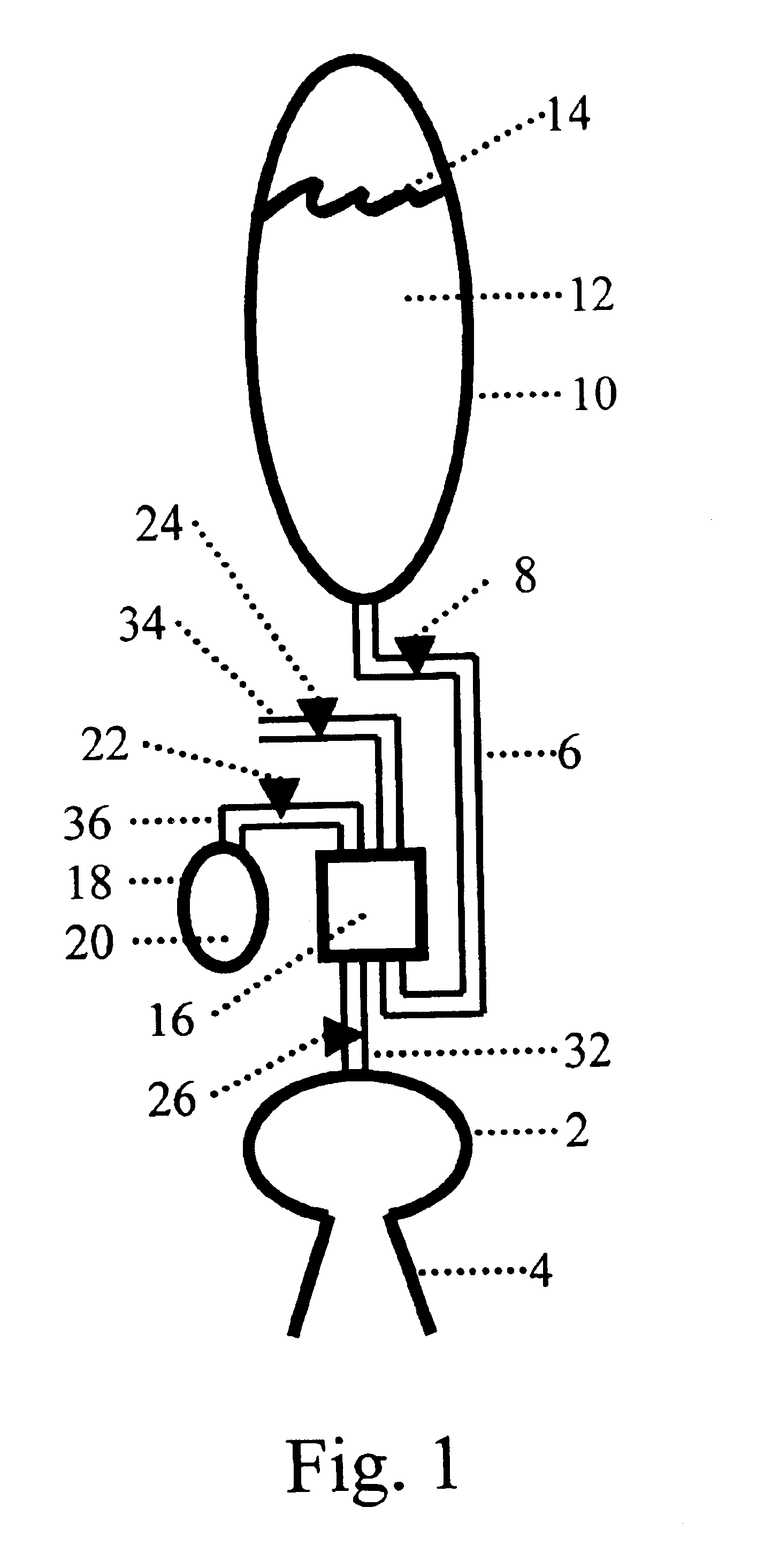
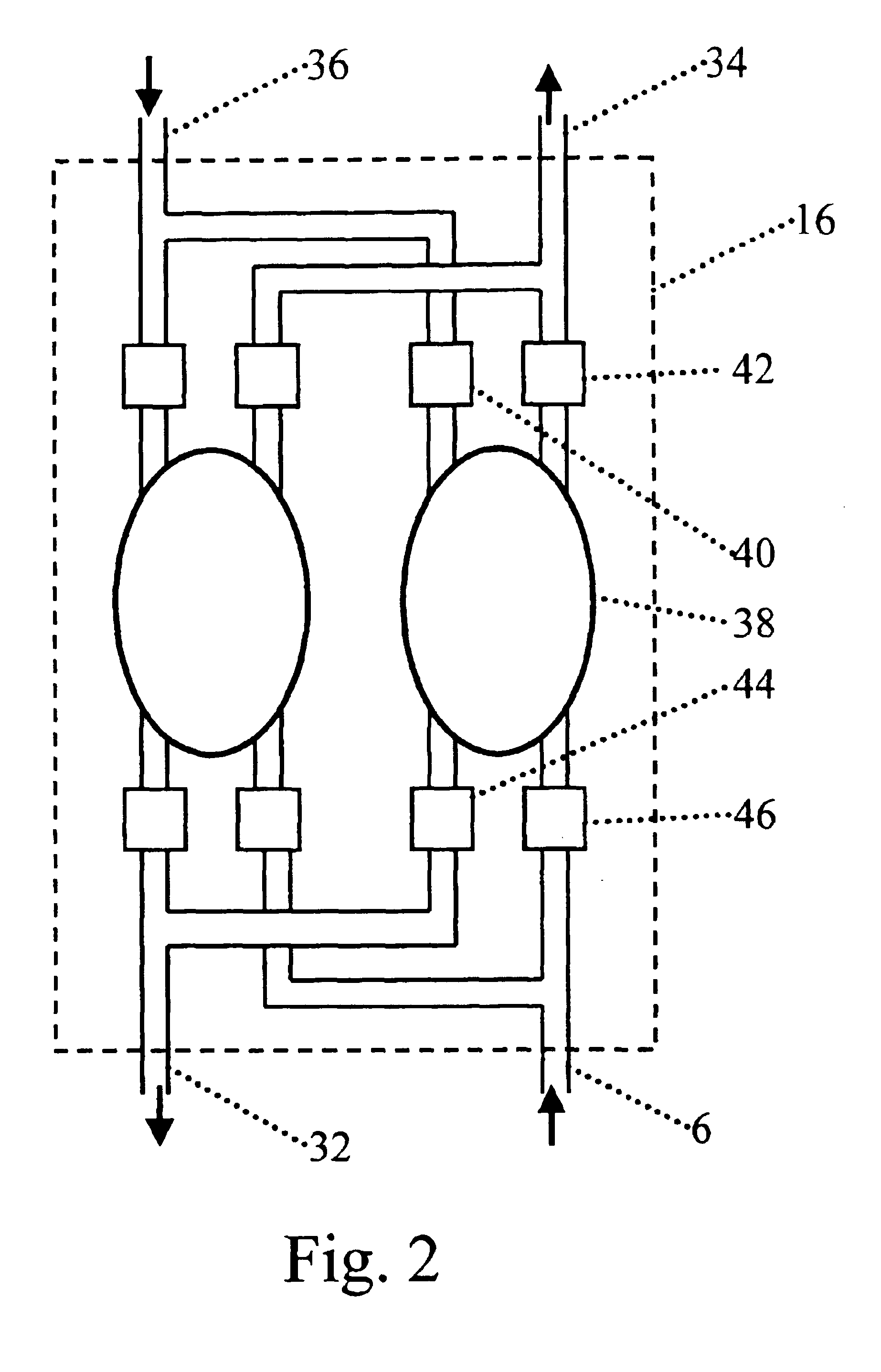
[0047]Referring to FIG. 1, according to a preferred embodiment, a rocket engine system includes a propellant tank 10 connected by a propellant conduit 6 to a pressurizer 16, a pressurant tank 18 connected by a pressurant conduit 36 to the pressurizer 16, and an impulse reaction engine 2 (also known as a rocket engine 2 or jet engine 2) with a nozzle 4 connected by an engine conduit 32 to the pressurizer 16. The propellant tank 10 contains a propellant 12 with meniscus 14. Flow of the propellant 12 into pressurizer 16 is controlled by propellant valve 8. A pressurant tank 18 contains a pressurant 20. Flow of the pressurant 20 into pressurizer 16 is contro...


PUM


Abstract

A pressurizer for pressurizing a fluid includes: at least two storage tanks, where, for each storage tank, the pressurizer further includes: a propellant entrance valve, a propellant exit valve, a pressurant entrance valve, and a pressurant exit valve, where each of the storage tanks is configured to be filled with the fluid under a low pressure when its propellant entrance and pressurant exit valves are open and its propellant exit and pressurant entrance valves are closed, and to be drained of the fluid under a high pressure by the force of a pressurant when its valves are reversed, where its valves are configured to be opened and closed in a cycle to sequentially fill and drain the storage tank of the fluid, the cycle having a cycle time of between 1 and 500 milliseconds, and where the cycles of the valves of the storage tanks are out of phase with each other such that at some time in which one storage tank is being filled with the fluid, at least one other storage tank is being drained of the fluid. The pressurizer may be used as a propellant pump in a rocket engine.

Description

REFERENCE TO RELATED APPLICATION[0001]This application is a Continuation-in-Part (CIP) of U.S. application Ser. No. 10 / 214,706, entitled “Pressurizer For a Rocket Engine,” filed Aug. 9, 2002. and issued as U.S. Pat. No. 6,751,945.BACKGROUND[0002]Rocket engines require propellants to be fed to them at very high pressures. This has historically been accomplished in two general ways: first, with the use of a pressurized fluid, such as high pressure helium; and second, with the use of a pump.[0003]In the first way (e.g., a “blowdown” system), a pressurized fluid, such as helium, is added directly to the propellant tank and exerts a force on the propellant. The problem with this method, however, is that the pressurized fluid also exerts a force on the propellant tank. Because of the extremely high pressures required of the pressurized fluid, the walls of the propellant tank must be thick enough to withstand the pressure. The propellant tank is therefore very heavy. Rockets employing the ...

Claims


Application Information

Patent Timeline
IPC IPC(8): F02K9/00F02K9/42F02K9/72F02K9/50
CPCF02K9/50
Inventor KNIGHT, ANDREW F.
Owner KNIGHT ANDREW F
Why Eureka
Try Eureka