Moulding apparatus

a technology of straps and moulding parts, which is applied in the direction of nanobatteries, sustainable manufacturing/processing, cell components, etc., can solve the problems of tail formation, no proper joint formation, and submerged surface of lugs melting

Inactive Publication Date: 2006-08-01
TBS ENG LTD
View PDF6 Cites 11 Cited by
  • Summary
  • Abstract
  • Description
  • Claims
  • Application Information

AI Technical Summary

Benefits of technology

[0005]Preferably the temperature change at each interface is between 100° C. to 275° C. It is further preferred that the interface at the top of each weir is less than 10 mm thick.
[0006]The mould and the inlet and

Problems solved by technology

However, as the size of the lugs increase, so does the capacity of the effective heat sink which has been dipped into the molten lead, with the result that the lead can be cooled so rapidly that the submerged surface of the lugs does not melt and no proper joint is formed.
In an attempt to overcome this, systems have been developed whereby lead is flowed through the mould, at least during an initial dipping step, so that the l

Method used


Image

  • Moulding apparatus
  • Moulding apparatus
  • Moulding apparatus

Examples


Embodiment Construction

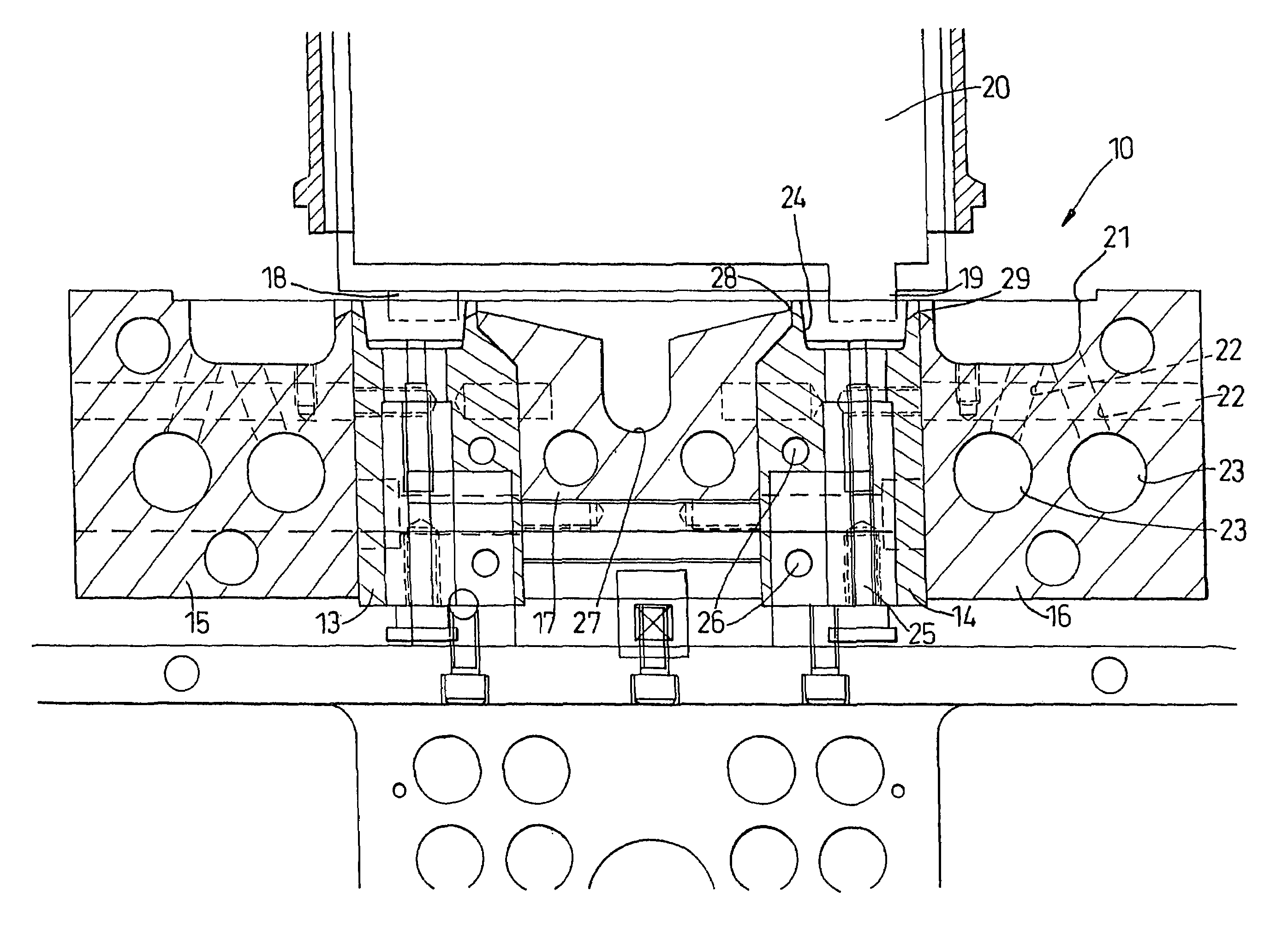
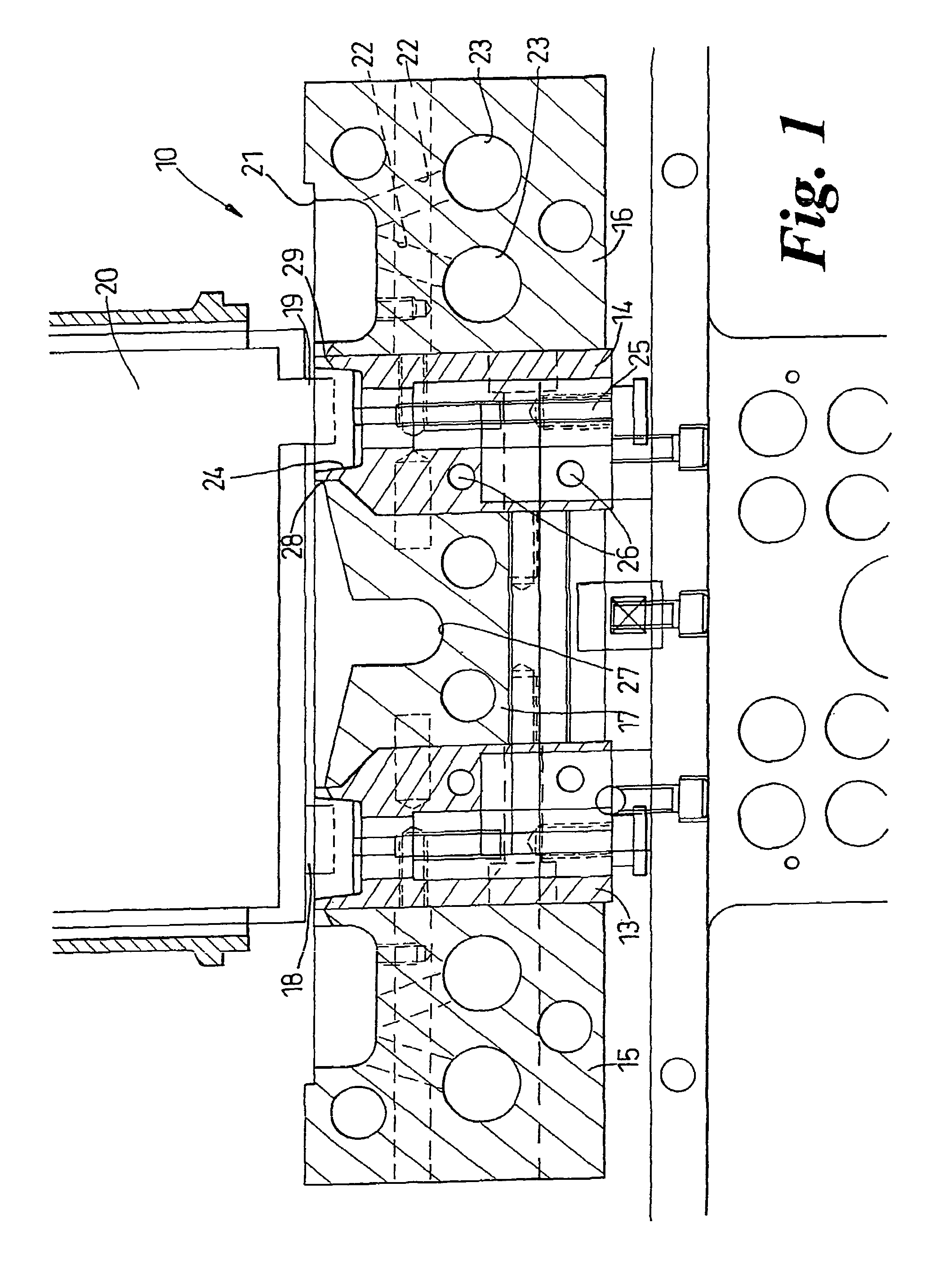
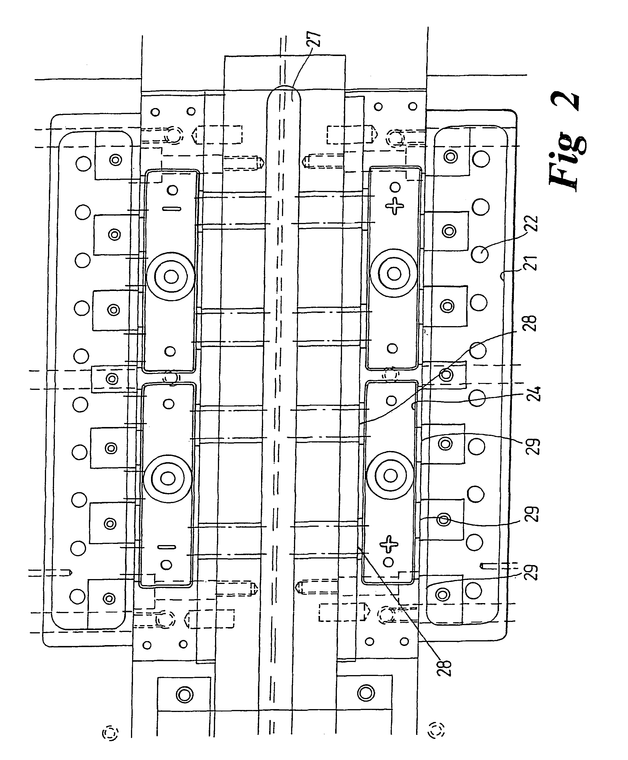
[0014]Broadly the apparatus, which is generally indicated at 10, comprises a pair of mould blocks 13,14, respective lead inlet blocks 15, 16 and a common lead outlet block 17. The combination of 13,15, and 17, operates identically to the combination 14,16,17 and the construction and operation of the apparatus 10 will be described solely in connection with the latter combination. Two combinations are required, so that straps can be formed simultaneously on the positive lugs 18 and the negative lugs 19 of the battery plates 20.

[0015]The lead block 16 has a lead reservoir, in the form of channel 21 into which lead can upwardly well through shafts 22 that are connected to respective supply pipes 23, which are in turn supplied by a lead pot not shown. The bulk of the block 16 is maintained at an elevated temperature of around 400 to 500° C., which is substantially above the melting point of the lead alloys used in the process, which melt, typically, between 250 and 310° C.

[0016]The mould...


PUM

PropertyMeasurementUnit
Temperatureaaaaaaaaaa
Lengthaaaaaaaaaa

Abstract

A moulding apparatus (10) for moulding a strap on to a group of battery plates including a mould block (14) with moulds (24), each of which has an inlet weir (28) and an outlet weir (29). The ridge (30) of these weirs is effectively a knife edge but includes a thermal break. This construction allows rapid processing whilst avoiding the formation of solid tails.

Description

CROSS-REFERENCE TO RELATED APPLICATION[0001]This application is a 371 of PCT / GB01 / 05441 filed on Dec. 10, 2001.BACKGROUND OF THE INVENTION[0002]This invention relates to apparatus for moulding a strap on a group of battery plates.[0003]The most common method of moulding straps on groups of battery plates is to invert the group and dip the lugs into a mould filled with molten, but cooling, lead. With thin lugs this is relatively straight forward, because there is sufficient heat in the cooling lead to fuse them and form a good joint. However, as the size of the lugs increase, so does the capacity of the effective heat sink which has been dipped into the molten lead, with the result that the lead can be cooled so rapidly that the submerged surface of the lugs does not melt and no proper joint is formed. In an attempt to overcome this, systems have been developed whereby lead is flowed through the mould, at least during an initial dipping step, so that the lead temperature is initially...

Claims


Application Information

Patent Timeline
IPC IPC(8): B22D41/00B22D19/04B22D25/04H01M10/04H01M50/541
CPCB22D19/04H01M2/28B22D25/04H01M2010/0495Y02E60/10H01M50/541Y02P70/50
Inventor HOPWOOD, ROBERT T.
Owner TBS ENG LTD
Why Eureka
Try Eureka