Full-bore artillery projectile fin development device and method

a technology of full-bore artillery and projectiles, applied in the direction of direction controllers, wings, transportation and packaging, etc., can solve the problems of excessive angular acceleration of the entire projectile, prohibitively high inertial forces acting on the projectile components, and malfunction and failure of the detonation

Inactive Publication Date: 2006-08-01
UNITED STATES OF AMERICA THE AS REPRESENTED BY THE SEC OF THE ARMY
View PDF16 Cites 46 Cited by
  • Summary
  • Abstract
  • Description
  • Claims
  • Application Information

AI Technical Summary

Problems solved by technology

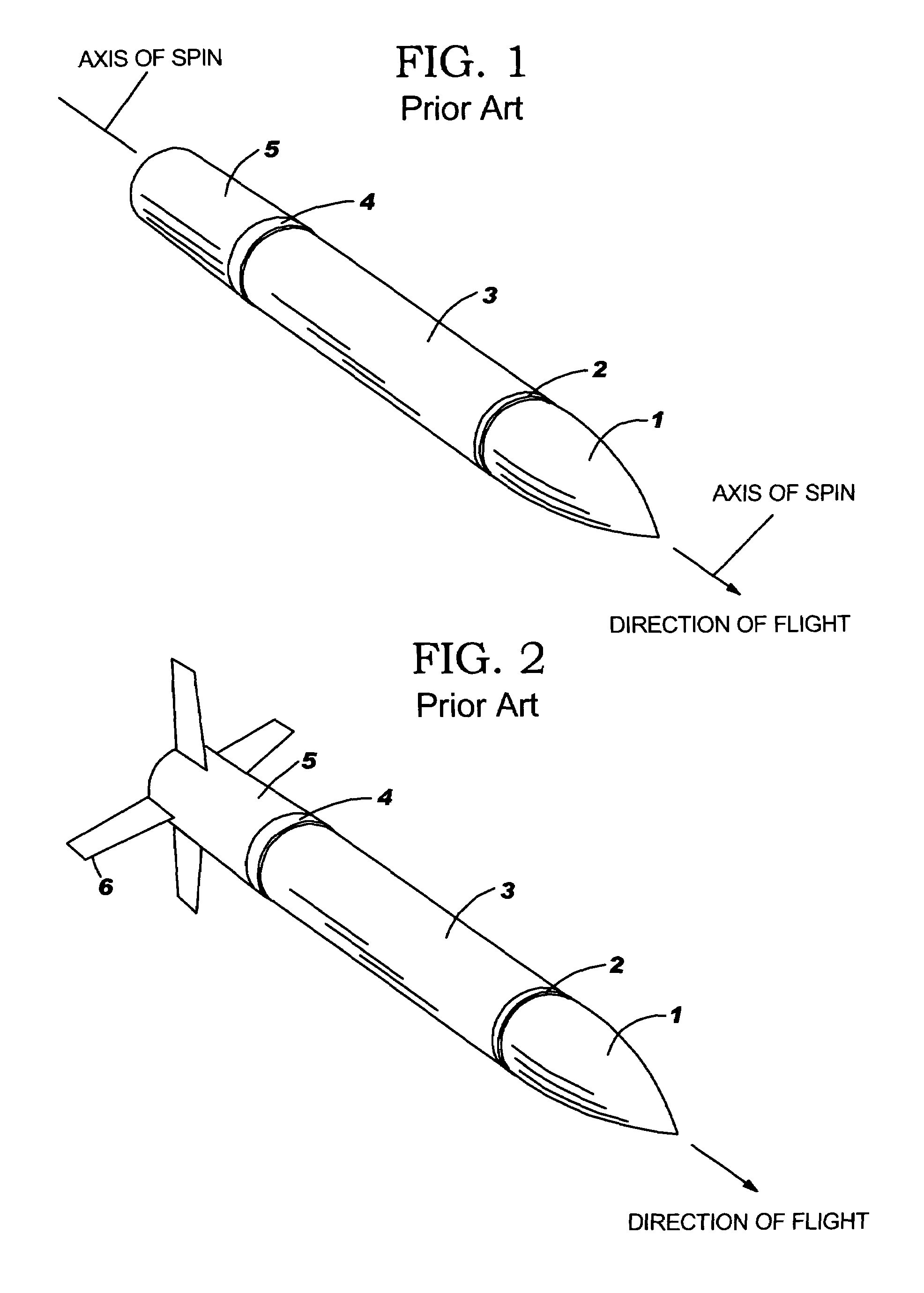
One disadvantage associated with the spin stabilization method is the potential for excessive angular acceleration imparted to the entire projectile.
The associated axial and centrifugal loads may result in prohibitively high inertial forces acting on projectile components.
In these cases, the projectile may approach or impact the target at an orientation other than nose (ogive 1) first thereby resulting in a malfunction and a failed or delayed detonation.
Another characteristic of over-stabilized projectiles is their tendency to drift off their intended trajectories resulting in excessive dispersion and / or unintended collateral damage.
A disadvantage of the fin stabilization method is that the fins must be capable of assuming a stowed configuration for translation through the bore of the cannon during launch, and a deployed configuration for aerodynamic stability during flight.
Some potential complications associated with these devices include a possible requirement that they integrate precise timing mechanisms or electrical circuits to activate and deploy the fins within a short distance after the projectile exits the muzzle of the cannon.

Method used


Image

  • Full-bore artillery projectile fin development device and method
  • Full-bore artillery projectile fin development device and method
  • Full-bore artillery projectile fin development device and method

Examples


Embodiment Construction

[0035]The embodiments of the invention and the various features and advantageous details thereof are explained more fully with reference to the non-limiting embodiments that are illustrated in the accompanying drawings and detailed in the following description. It should be noted that the features illustrated in the drawings are not necessarily drawn to scale. Descriptions of well-known components and processing techniques are omitted so as to not unnecessarily obscure the embodiments of the invention. The examples used herein are intended merely to facilitate an understanding of ways in which the embodiments of the invention may be practiced and to further enable those of skill in the art to practice the embodiments of the invention. Accordingly, the examples should not be construed as limiting the scope of the embodiments of the invention.

[0036]As mentioned, there remains a need for a novel full-bore artillery projectile fin deployment mechanism which is not dependent on the use o...


PUM


Abstract

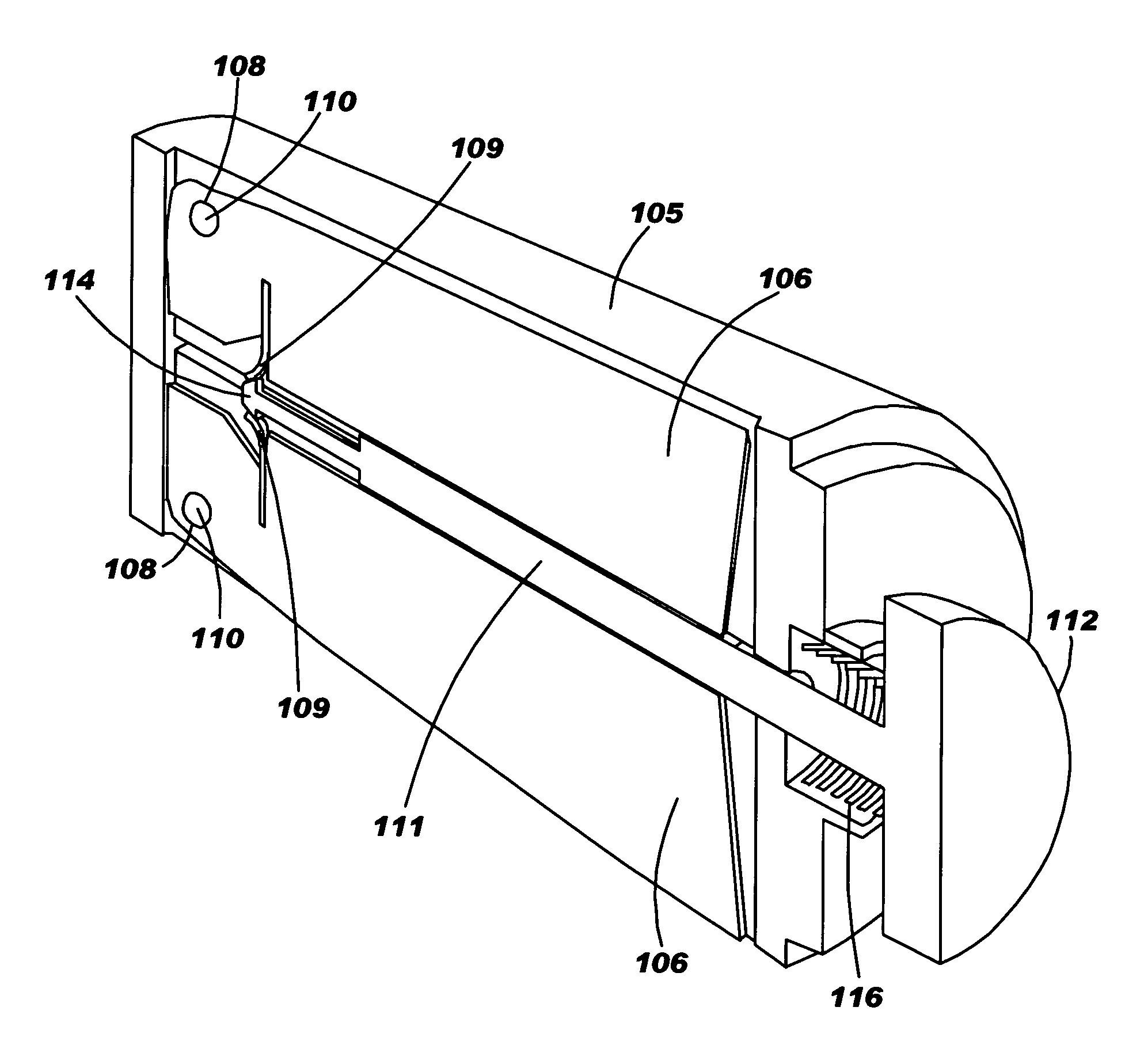
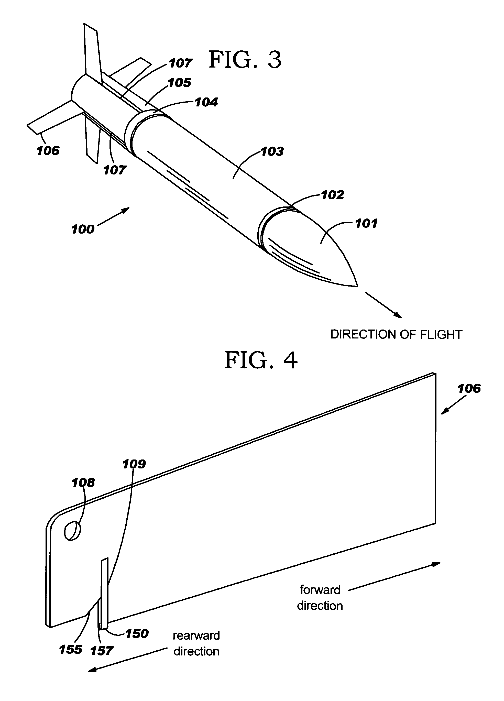
A method and structure for a full-bore artillery projectile fin deployment device comprising a projectile stabilization fin comprising an aperture and a movable pawl; a rod comprising a head portion and a shaft portion terminating with a beveled tip configured for engaging the pawl; a tailboom configured for housing the fin, wherein the tailboom comprises a hollow bore configured for receiving the rod; a pin slotted through the aperture and attached to the tailboom; and a bias member adjacent to the head portion of the rod. The rod is slotted to simultaneously engage a plurality of fins. The tailboom comprises a forward end and a rearward end and a slot configured for permitting the fin to articulate out of the tailboom, and wherein the tailboom connects to a projectile. Additionally, the power source for the device is the naturally occurring launch accelerations.

Description

GOVERNMENT INTEREST[0001]The invention described herein may be manufactured, used, and / or licensed by or for the United States Government.BACKGROUND OF THE INVENTION[0002]1. Field of the Invention[0003]The invention generally relates to guided projectiles, and more particularly to a fin-stabilized guided projectile.[0004]2. Description of the Related Art[0005]Generally, artillery projectiles launched from cannons require mechanical and aerodynamic stabilization to assure a predictable trajectory. Until recently, most artillery projectiles were generally stabilized by means of angular momentum (spinning inertia). This technique commonly referred to as spin stabilization, is achieved by spinning the projectile about its longitudinal axis as it translates along the bore of the cannon. FIG. 1 shows an example of the general configuration of a conventional spin stabilized projectile consisting of an ogive 1 adjacent to a forward bore rider 2, which is next to a shell body 3 that is adjac...

Claims


Application Information

Patent Timeline
Patent Type & Authority Patents(United States)
IPC IPC(8): F42B10/14
CPCF42B10/14
Inventor DOOLEY, ROBERT B.
Owner UNITED STATES OF AMERICA THE AS REPRESENTED BY THE SEC OF THE ARMY
Why Eureka
Try Eureka