
Double-acting load floor slam latch

a floor slam latch, double-acting technology, applied in the field of latches, can solve the problems of putting the vehicle operator in danger, the latch becomes unsecured, and the danger of the operator, and achieve the effect of reducing the movement of the handl

Inactive Publication Date: 2006-08-01
SOUTHCO
View PDF40 Cites 38 Cited by
  • Summary
  • Abstract
  • Description
  • Claims
  • Application Information

AI Technical Summary

Benefits of technology

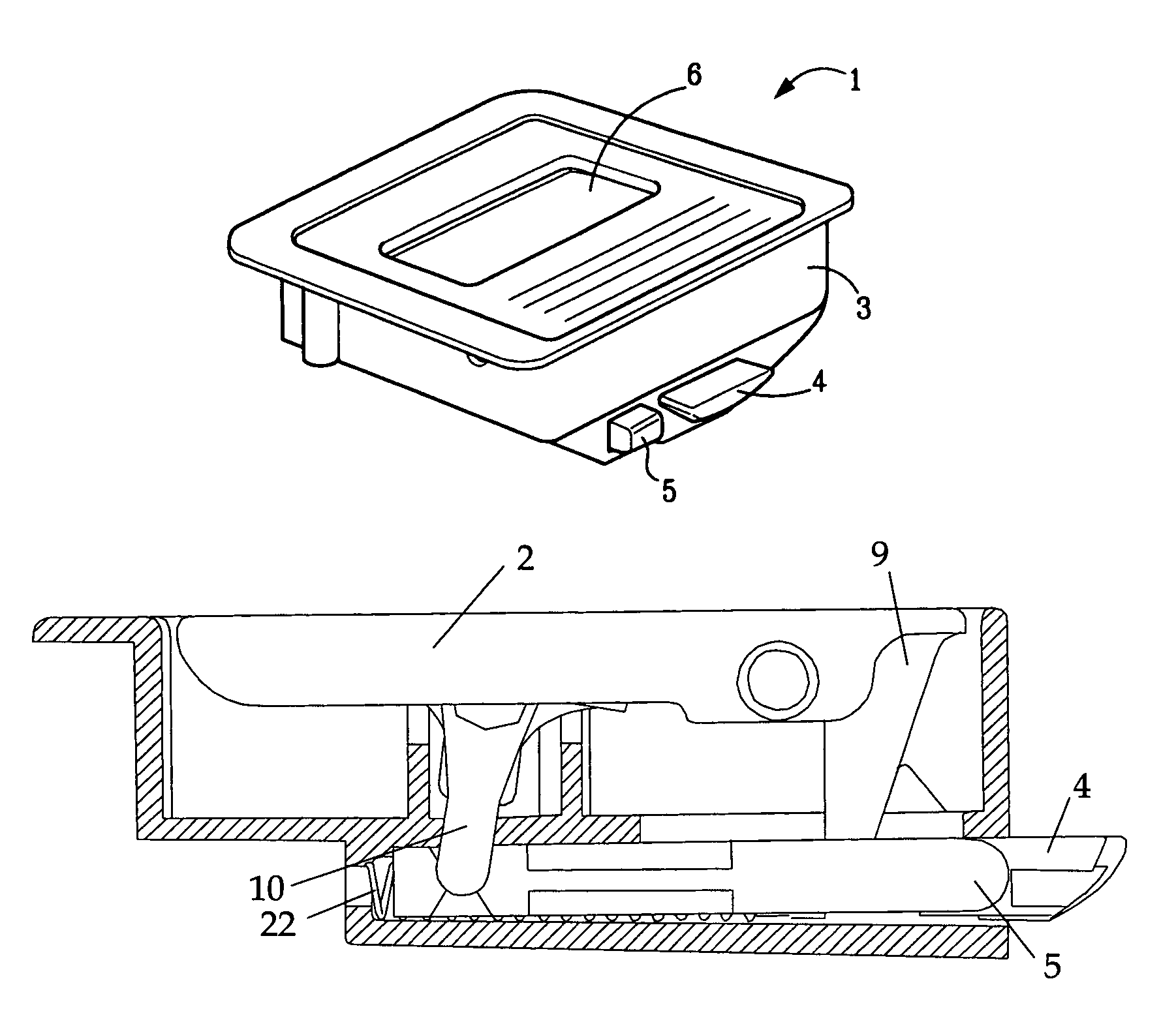
[0010]The present invention in one embodiment comprises a housing, a handle and a rocker mounted in the housing, a main pawl, a secondary side pawl and a main pawl spring. The main pawl of the latch is configured to be positioned in a panel and thereby secure the panel in a frame. The main pawl extends through the frame and when the latch is in the closed position, the main pawl is secured to the keeper. The secondary side pawl is provided such that it secures only a portion of the panel to the frame. To place the entire panel in an open position, the secondary side pawl is placed into a locked and closed position and the secondary side pawl engages the frame. To open only a defined portion of the panel the secondary side pawl must be in the open position such that the secondary side pawl clears the frame when that portion of the panel is opened. To open either the entire panel or only a portion of the panel, the handle is opened by a user and the handle actuates the main pawl and releases the panel from the load floor. A biasing means provides a biasing force on the main pawl such that when the user desires that the panel be closed such that the main pawl engages the keeper and the panel is secured, the panel can be lowered and a force applied to an outer face of the panel causes the main pawl to contact the keeper. A linear force on the pawl results in the direction of the rear of the housing and the main pawl slides back into the housing. The main pawl can now move back into a position such that the main pawl fastens the panel in a closed position. The handle can be provided with a biasing means in order to minimize undesired movement of the handle which may cause rattling when the handle is in an at rest position.
[0011]The inwardly facing side of the rocker is provided with two plungers each of which is inside a tower. The plungers compress back into the towers due to interference with a detent device on the inside of the housing which the plungers face. This creates a detent effect similar to that of a light switch and provides for an open and a closed position of the rocker. A user can rotate the rocker which in turn activates the secondary side pawl.
[0015]Another object of the present invention is to provide a latch which has improved retention characteristics under stress forces, such as those experienced by vehicle rollovers and crashes.

Problems solved by technology

One drawback with the previous latches is that the latches did not provide for the ability to secure only a portion of a panel in a frame and therefore provide the user with the ability to open and close only a portion of the panel which is divided into portions.
Thus, in this type of vehicle, there is great danger to be encountered should a rollover of the vehicle occur and the latch becomes unsecured.
If this were to happen, the compartment contents would spill out into the passenger compartment, thereby placing the vehicle operator in danger.

Method used


Image

  • Double-acting load floor slam latch
  • Double-acting load floor slam latch
  • Double-acting load floor slam latch

Examples


Embodiment Construction

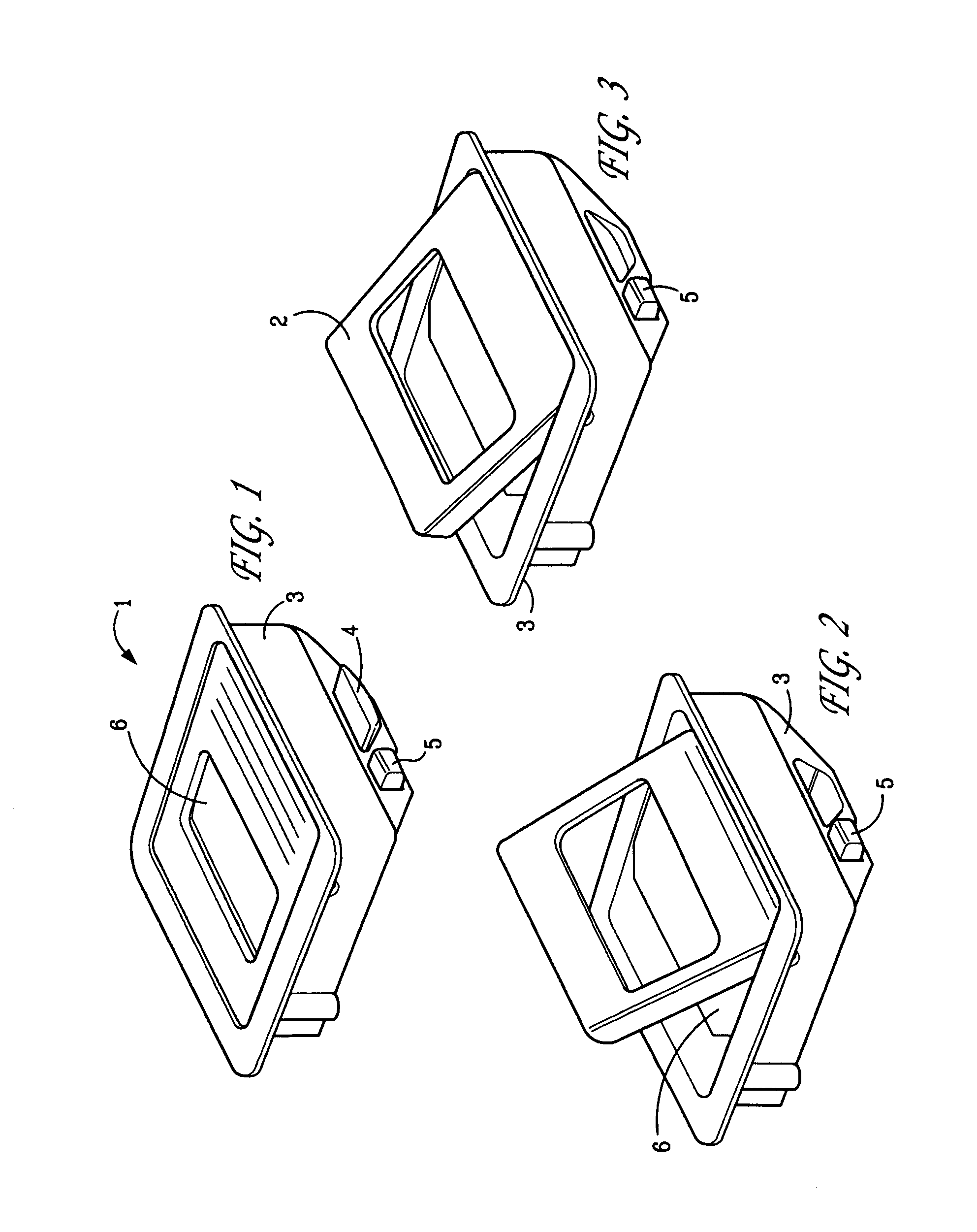
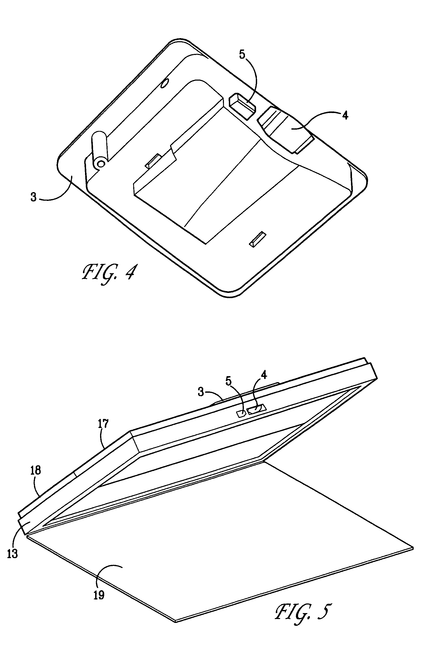
[0070]Referring now to the drawings in detail wherein like reference numerals indicate like elements through the several views, there is shown in FIG. 1–4, perspective views of a preferred embodiment of a latch 1 in accordance with the present invention with a housing 3, handle 2 and rocker 6. FIGS. 2 and 3 show the actuation of the main pawl 4 during rotation of handle 3. As the handle 2 is rotated from the rest position shown in FIG. 1, the main pawl 4 moves toward the rear of the housing 3 thereby placing the main pawl 4 in the open position so that the main pawl 4 no longer protrudes from the housing 3 as shown in FIG. 2. Secondary side pawl 5 is shown protruding from housing 3 in the closed position in FIGS. 1–4.

[0071]FIGS. 7–9 show the handle 2 of the latch 1. The handle 2 features a handle actuator 9 which pivots or rotates with the handle 2 and contacts an interior face 25 of the main pawl 4. As the main pawl 4 is pushed toward the rear of the housing 3 during movement of th...


PUM


Abstract

The present invention relates to a latch for securing together a panel to a keeper thus permitting opening and closing of a portion of the panel while allowing the remaining portion of the panel to remain closed. When the latch is unlatched from a keeper, a user can refasten the panel by lowering the panel until the main pawl and the keeper are fastened together by the action of the keeper on the pawl of the latch. The latch also provides for the opening and closing of a portion of one of the panels while allowing the remaining portion of that panel to remain closed.

Description

CROSS-REFERENCE TO RELATED APPLICATIONS[0001]This application claims the benefit under 35 U.S.C. 119(e) of U.S. provisional patent application No. 60 / 411,321 filed Sep. 17, 2002 entitled Double Acting Load Floor Slam Latch the entire specification of which is incorporated by reference.BACKGROUND OF THE INVENTION[0002]The present invention relates to a latch for securing together a panel in a frame to a keeper and provides for the opening and closing of a portion of the panel while allowing the remaining portion of the panel to remain closed. The latch can be repeatedly latched and unlatched by a user who desires to fasten and unfasten the entire panel or a portion of the panel which is adjacent the keeper.[0003]Various latches are known for securing a panel to a keeper. One drawback with the previous latches is that the latches did not provide for the ability to secure only a portion of a panel in a frame and therefore provide the user with the ability to open and close only a porti...

Claims


Application Information

Patent Timeline
IPC IPC(8): E05C9/10E05B63/14E05C1/14
CPCE05C1/145E05B63/14Y10T292/0837Y10T292/089Y10T292/0997
Inventor HALL, MATTHEW
Owner SOUTHCO
Learn More