Inkjet printer cartridge with uniform compressed air distribution

a printer cartridge and compressed air technology, applied in printing and other directions, can solve the problems of affecting the quality of inkjet printing, and difficulty in removing and replacing printheads, so as to prevent degradation of print quality, and ensure the effect of printing quality

a printer cartridge and compressed air technology, applied in printing and other directions, can solve the problems of affecting the quality of inkjet printing, and difficulty in removing and replacing printheads, so as to prevent degradation of print quality, and ensure the effect of printing quality

US7083273B2Active Publication Date: 2006-08-01SILVERBROOK RES PTY LTD +1

Image

  • Inkjet printer cartridge with uniform compressed air distribution
  • Inkjet printer cartridge with uniform compressed air distribution
  • Inkjet printer cartridge with uniform compressed air distribution

Examples


Embodiment Construction

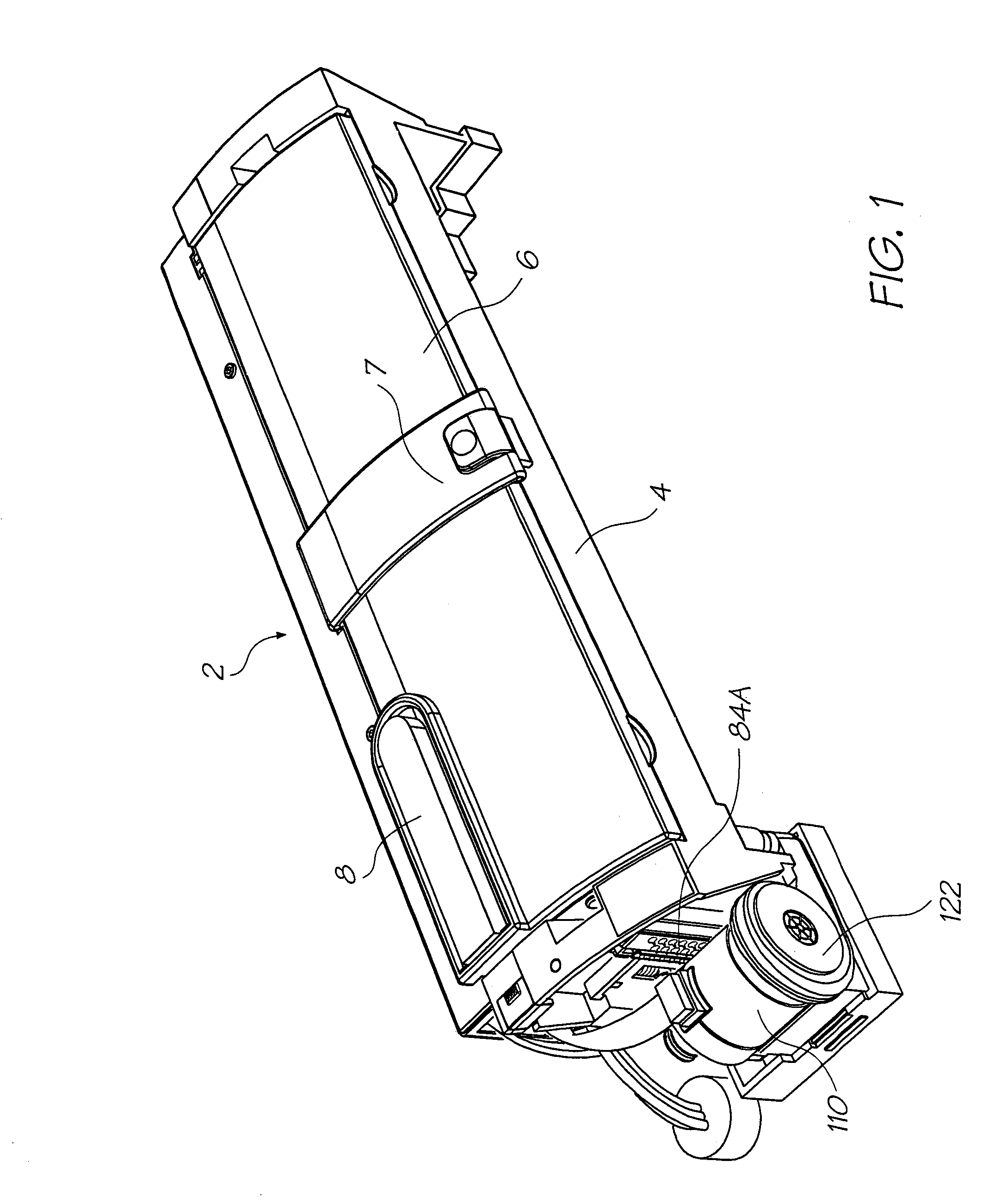
[0055]FIG. 1 depicts an inkjet printer 2 which includes a cradle 4 that receives a replaceable print cartridge 6 into a recess formed in the cradle's body according to a preferred embodiment of the present invention. Cartridge 6 is secured in the cradle recess by a retainer in the form of latch 7 that is connected by a hinge to cradle 4. Visible on the upper surface of print cartridge 6 is an ink refill port 8 which receives an ink refill cartridge during use.

Print Cartridge

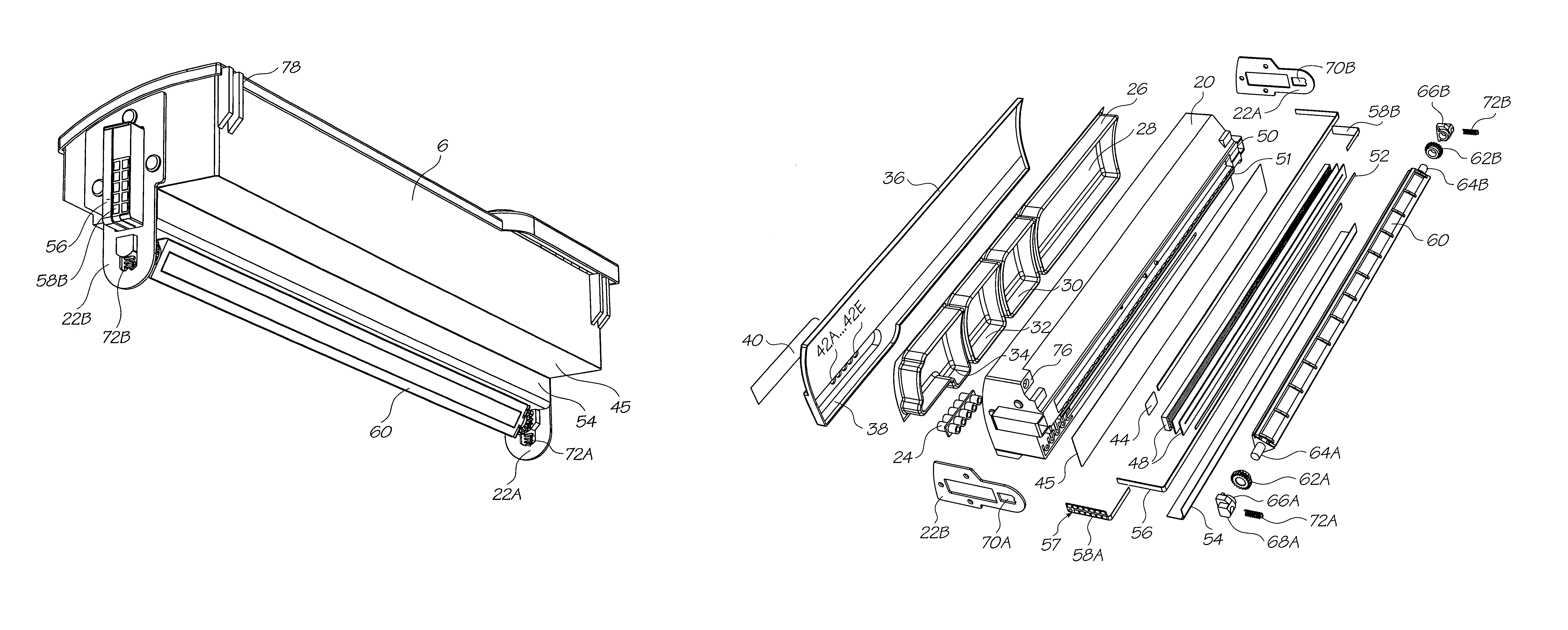
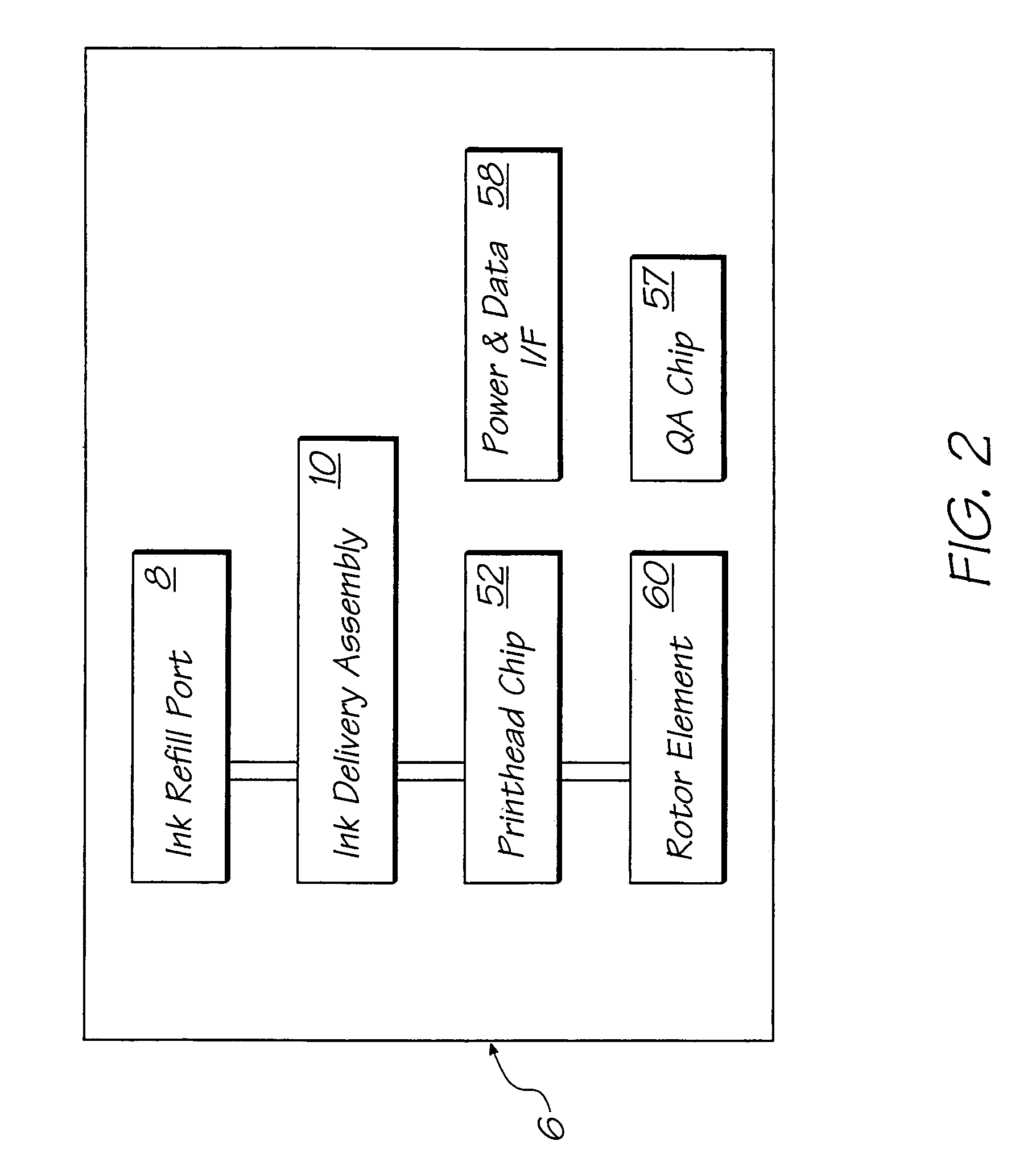
[0056]Referring now to FIG. 2, there is depicted a block diagram of removable inkjet printer cartridge 6. Cartridge 6 includes ink refill port 8 and an ink delivery assembly 10 for storing and delivering ink to a micro-electromechanical pagewidth print head chip 52. Printhead chip 52 receives power and data signals from cradle 4 (see FIG. 1) via power and data interface 58. A rotor element 60, which is mechanically driven by cradle 4 has three faces which respectively serve to: blot printhead chip 52 subsequent t...


PUM


Abstract

An inkjet printer cartridge including an elongate body housing a printing fluid storage and adapted to be received within an inkjet printer cradle, a pagewidth printhead attached to the body and in fluid communication with the printing fluid storage, and an air distribution assembly arranged to evenly distribute compressed air along the pagewidth printhead.

Description

FIELD OF THE INVENTION[0001]The present invention relates to a printer system and in particular to a removable printer cartridge for an inkjet printer system.CROSS-REFERENCE TO CO-PENDING APPLICATIONS[0002]The following applications have been filed by the Applicant simultaneously with the present application:[0003]10 / 76023010 / 76022510 / 76022410 / 76024210 / 76022810 / 76025010 / 76021510 / 76025610 / 76025710 / 76024010 / 76025110 / 76026610 / 76023910 / 76019310 / 76021410 / 76026010 / 76022610 / 76026910 / 76019910 / 76024110 / 76027210 / 76027310 / 76018710 / 76018210 / 76018810 / 76021810 / 76021710 / 76021610 / 76023310 / 76024610 / 76021210 / 76024310 / 76020110 / 76018510 / 76025310 / 76025510 / 76020910 / 76020810 / 76019410 / 76023810 / 76023410 / 76023510 / 76018310 / 76018910 / 76026210 / 76023210 / 76023110 / 76020010 / 76019010 / 76019110 / 76022710 / 76020710 / 76018110 / 76025410 / 76021010 / 76020210 / 76019710 / 76019810 / 76024910 / 76026310 / 76024710 / 76022310 / 76026410 / 76024410 / 76024510 / 76022210 / 76024810 / 76023610 / 76019210 / 76020310 / 76020410 / 76020510 / 76020610 / 76026710 / 76027010 / 760...

Claims


Application Information

Patent Timeline
01 Aug 2006
Publication
US7083273B2
IPC
B41J2/175; B41J2/165; B41J2/155
CPC
B41J2/155; B41J2/17596; B41J2/17563
Inventors
SILVERBROOK, KIA