Floating connector spring and assembly

a technology of connecting springs and connectors, applied in the direction of machine supports, coupling device connections, other domestic objects, etc., can solve the problems of inability to properly mate, inability to properly compensate for connectors that may be out of alignment, and difficulty in trying to mating if not impossibl

Active Publication Date: 2006-08-01
LENOVO PC INT
View PDF12 Cites 9 Cited by
  • Summary
  • Abstract
  • Description
  • Claims
  • Application Information

AI Technical Summary

Benefits of technology

[0004]The present invention provides a novel floating connector spring that allows a connector body to move in multiple degrees of freedom as necessary to compensate for any misalignment between the two connector bodies to be mated. Broadly, the connector spring includes first and second spring arms spaced from one another and which extend substantially in the same direction. Each of the first and second spring arms have a proximal end and a distal end and at least one lobe section disposed between the proximal and distal ends, and each of the lobe sections are configured to be resiliently deformable, including being expandable and compressible, to allow movement of the distal ends relative to the proximal ends of the first and second spring arms. The connector is preferably mounted between the first and second arms adjacent the distal ends of the arms.

Problems solved by technology

Any misalignment between the two bodies may make the attempted mating difficult if not impossible.
The connectors, fixedly or rigidly mounted on their respective circuit boards, may be out of alignment in any of six degrees of freedom due to manufacturing tolerances, and thus unable to properly mate.
Nevertheless, none of them can sufficiently compensate for a connector that may be out of alignment in up to six degrees of freedom.

Method used


Image

  • Floating connector spring and assembly
  • Floating connector spring and assembly
  • Floating connector spring and assembly

Examples


Embodiment Construction

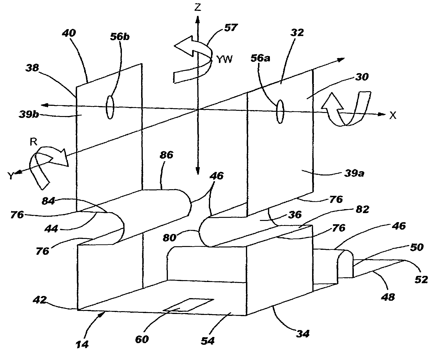
[0019]The present invention is now described with reference to an electrical connector assembly. Although a connector assembly as used with an electrical connector is described for illustrative purposes, the present invention is not so limited. For example, the present invention may apply equally to other bodies to be connected where the bodies are misaligned.

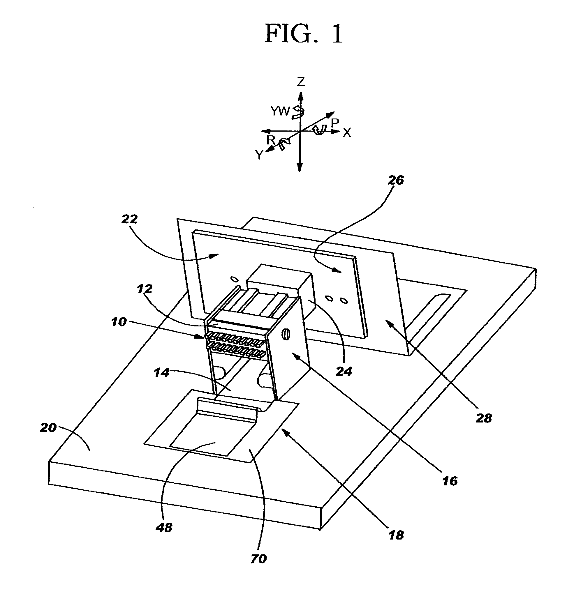
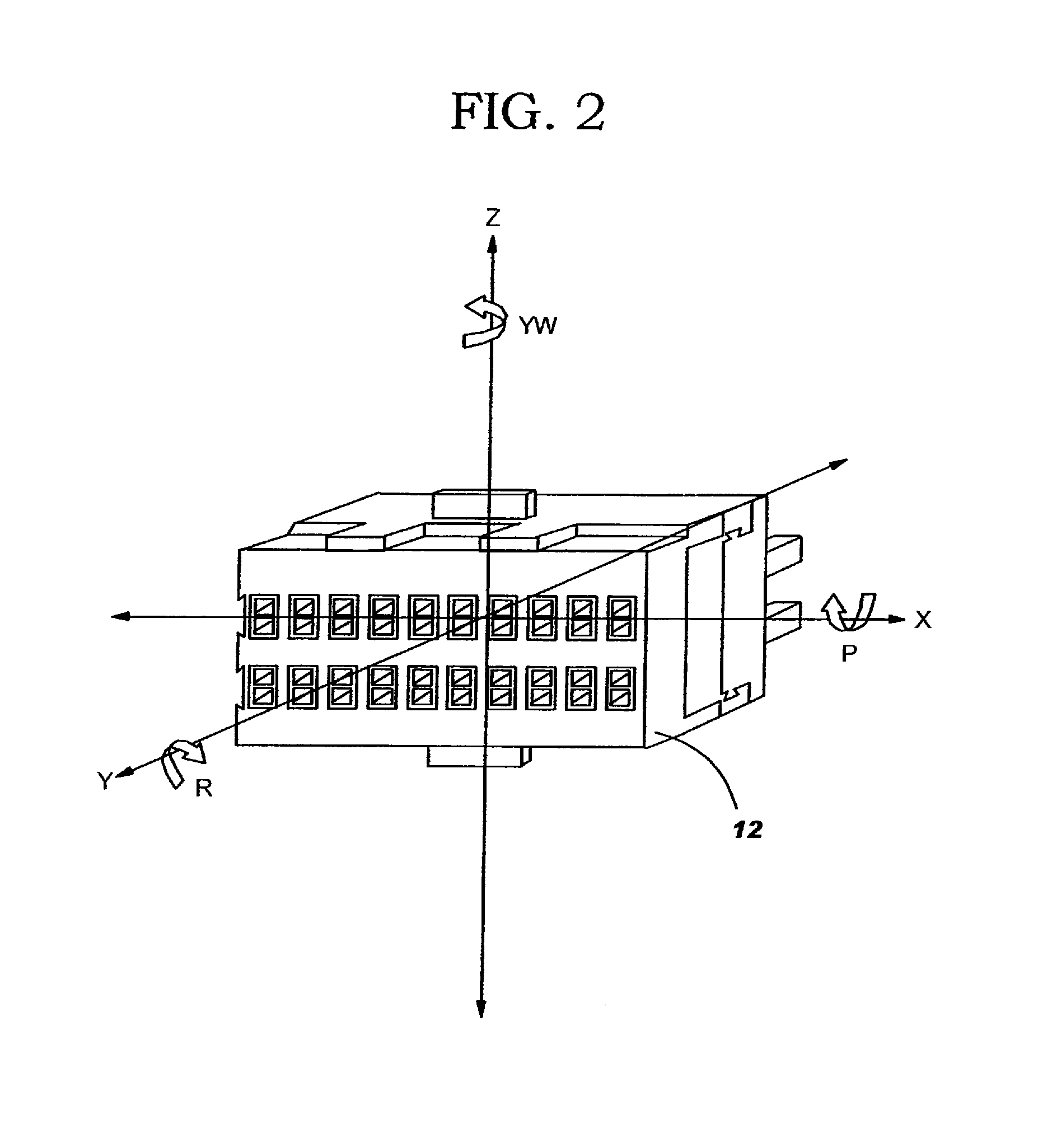
[0020]With reference to FIG. 1, a presently preferred connector to connector mating system incorporating the present invention is illustrated. A first connector assembly 10 includes an electrical connector 12, a floating connector spring 14 to which the electrical connector 12 is mounted, and a restrainer 16 positioned to limit the movements of the connector spring 14. The connector spring 14 in combination with the restrainer 16 is referred to herein as a spring / restrainer assembly 18. The connector assembly 10 is mounted to a base 20 and allows the connector 12 to move in any of six degrees of freedom as necessary for alignme...


PUM


Abstract

A floating connector spring capable of movement in multiple degrees of freedom to enable the mating of at least two connectors that may be misaligned relative to one another. The connector spring includes first and second arms spaced form one another and extending substantially in the same direction. The first and second arms each have a lobe section between their distal and proximal ends, which are resiliently deformable to allow movement of the distal ends relative to the proximal ends of the respective arms. The movement permitted includes linear and rotational movement in up to six degrees of freedom depending on the configuration of the invention used. The connector spring can further include a third arm extending perpendicular from the first and second arms and which includes a third lobe section for movement in an additional degree of freedom. The connector spring can fixedly hold a connector, such as an electrical connector, and can further include a restrainer for limiting the range of motion of the spring.

Description

BACKGROUND OF THE INVENTION[0001]The present invention relates generally to connectors for connecting two bodies and, more particularly, to a connector assembly and spring that compensates for misalignment between the two bodies to be connected. The present invention is particularly relevant for electrical connectors.DESCRIPTION OF THE RELATED ART[0002]The mechanical mating / connection of two bodies, such as electrical connectors, generally requires that the two bodies be aligned within given positional tolerances. Any misalignment between the two bodies may make the attempted mating difficult if not impossible. For example, in electronic equipment, such as computers or servers, two circuit boards may need to be electrically connected via electrical connectors that are mounted in a fixed position to their respective circuit boards (as opposed to connectors attached to flexible or ribbon cable harnesses which are flexible and easily manipulated by hand for manual mating). One board ma...

Claims


Application Information

Patent Timeline
Patent Type & Authority Patents(United States)
IPC IPC(8): H01R13/64
CPCH01R13/6315
Inventor HERRING, DEAN F.LOPEZ, ANGELASASS, TONY C.WORMSBECHER, PAUL A.
Owner LENOVO PC INT
Why Eureka
Try Eureka