
Apparatus and method for dynamic alignment of source synchronous bus signals

a technology of synchronous bus signals and apparatus, applied in the field of microelectronics, can solve problems such as skewing of data signals and/or their strobes, error-prone source synchronous data strobes and data signals, and uncontrollable design margins

Active Publication Date: 2014-07-24
VIA TECH INC
View PDF0 Cites 5 Cited by
  • Summary
  • Abstract
  • Description
  • Claims
  • Application Information

AI Technical Summary

Benefits of technology

The patent text describes a method for compensating for misalignment on a synchronous data bus. This is accomplished by measuring the time it takes for a strobe signal to propagate from one part of the data bus to another and using this information to generate a value that represents the time it takes for the data bit to be registered by the destination. This method helps to ensure that data is transmitted and received in the correct order, which can improve the overall performance and reliability of the data bus.

Problems solved by technology

Yet, source synchronous data strobes and data signals are subject to error for a number of different reasons.
These inaccuracies may be the result of uncontrollable design margins, fabrication tolerances, or environmental factors such as voltage or temperature.
However, inaccuracies resulting from the above factors may result in skewing of the data signals and / or their strobes such that reception conditions are not optimum.
Consequently, operating frequency of associated devices is limited.
Another source of error may be caused by distribution of a strobe signal within a receiving device.
Some techniques for distributing a strobe signal to internal receivers simply adds propagation lengths that are required to route the strobe to the internal receivers, which may add delay over that of the data signals, thereby skewing the phase of the synchronous transmission.

Method used


Image

  • Apparatus and method for dynamic alignment of source synchronous bus signals
  • Apparatus and method for dynamic alignment of source synchronous bus signals
  • Apparatus and method for dynamic alignment of source synchronous bus signals

Examples


Embodiment Construction

[0027]Exemplary and illustrative embodiments of the invention are described below. In the interest of clarity, not all features of an actual implementation are described in this specification, for those skilled in the art will appreciate that in the development of any such actual embodiment, numerous implementation-specific decisions are made to achieve specific goals, such as compliance with system-related and business related constraints, which vary from one implementation to another. Furthermore, it will be appreciated that such a development effort might be complex and time-consuming, but would nevertheless be a routine undertaking for those of ordinary skill in the art having the benefit of this disclosure. Various modifications to the preferred embodiment will be apparent to those skilled in the art, and the general principles defined herein may be applied to other embodiments. Therefore, the present invention is not intended to be limited to the particular embodiments shown a...


PUM


Abstract

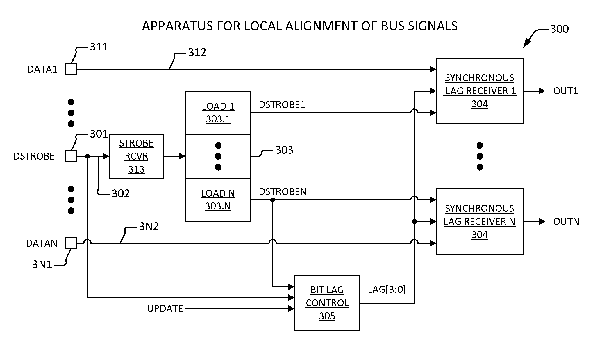
An apparatus that compensates for misalignment on a synchronous data bus. The apparatus includes a replica distribution network, a bit lag control element, and a synchronous lag receiver. The replica distribution network receives a first signal, and generates a second signal, where the replica distribution network comprises replicated propagation characteristics of a radial distribution network for a strobe. The bit lag control element is configured to measure a propagation time beginning with assertion of the first signal and ending with assertion of the second signal, and is configured to generate a value on a lag bus that indicates the propagation time. The synchronous lag receiver is coupled to the bit lag control element, and is configured to receive a first one of a plurality of radially distributed strobes and a data bit, and is configured to delay registering of the data bit by the propagation time.

Description

CROSS-REFERENCE TO RELATED APPLICATIONS[0001]This application is related to the following co-pending U.S. patent applications, each of which has a common assignee and common inventors.SER.FILINGNO.DATETITLE      XX / XX / XXXXAPPARATUS AND METHOD FOR(CNTR.2539)LOCALLY OPTIMIZING SOURCESYNCHRONOUS BUS SIGNALS      XX / XX / XXXXSOURCE SYNCHRONOUS BUS(CNTR.2576)SIGNAL ALIGNMENTCOMPENSATION MECHANISMBACKGROUND OF THE INVENTION[0002]1. Field of the Invention[0003]This invention relates in general to the field of microelectronics, and more particularly to an apparatus and method for synchronizing and clocks and data related to the transmission and reception of source synchronous signals.[0004]2. Description of the Related Art[0005]A present day computer system employs a source synchronous system bus to provide for exchange of data between bus agents, such as between a microprocessor and a memory hub. A “source synchronous” bus protocol allows for the transfer of data at very high bus speeds. Sou...

Claims


Application Information

Patent Timeline
Patent Type & Authority Applications(United States)
IPC IPC(8): G06F17/30
CPCG06F17/30581G06F13/4217G06F16/275
Inventor CANAC, VANESSA S.LUNDBERG, JAMES R.
Owner VIA TECH INC
Learn More