Improvements in or relating to on-axis melt pool sensors in an additive manufacturing apparatus

a technology of additive manufacturing and sensor, which is applied in the direction of manufacturing tools, additive manufacturing processes, manufacturing data acquisition/processing, etc., can solve the problem that the reading out of the values of all photodetector elements of such a large array may be unduly slow

Pending Publication Date: 2022-06-02
RENISHAW PLC
View PDF0 Cites 4 Cited by
  • Summary
  • Abstract
  • Description
  • Claims
  • Application Information

AI Technical Summary

Benefits of technology

[0029]In this way, the response of the on-axis melt-pool sensors can be adjusted such that both the first and second melt pool sensors give the same response for a melt pool formed under the same fluence conditions. In this way, the signals from the first and second melt-pool sensors can be displayed / processed together without the generation of artefacts as a result of differential responses between the first and second melt pool sensors for the same melting conditions.
[0030]In a preferred embodiment, the second optical train is controlled such that second melt pool sensor views the same melt pool as the first melt pool sensor. In this way, any differences in the melt pool viewed by the first and the second melt pool sensors is reduced or eliminated. It will be understood however, that in another embodiment the second optical train is controlled such that second melt pool sensor views a different melt pool but formed under the same fluence conditions. It would be expected that this further melt pool would generate substantially the same melt pool and plume and therefore, substantially the same response from the melt pool sensors, allowing the scaling to be determined from a comparison of the first and second signals. This may be necessary, for example, if scan fields of the first and second optical trains do not overlap.

Problems solved by technology

However, due to misalignment of the field of view of the on-axis sensor with the optical axis of the second optical train, the melt pool generated by the first laser beam may not be centred in the field of view at the one or more expected intersection points but may be centred within the field of view before or after the one or more expected intersection points.
However, to read out the values from all photodetector elements of such a large array may be unduly slow.

Method used


Image

  • Improvements in or relating to on-axis melt pool sensors in an additive manufacturing apparatus
  • Improvements in or relating to on-axis melt pool sensors in an additive manufacturing apparatus
  • Improvements in or relating to on-axis melt pool sensors in an additive manufacturing apparatus

Examples


Embodiment Construction

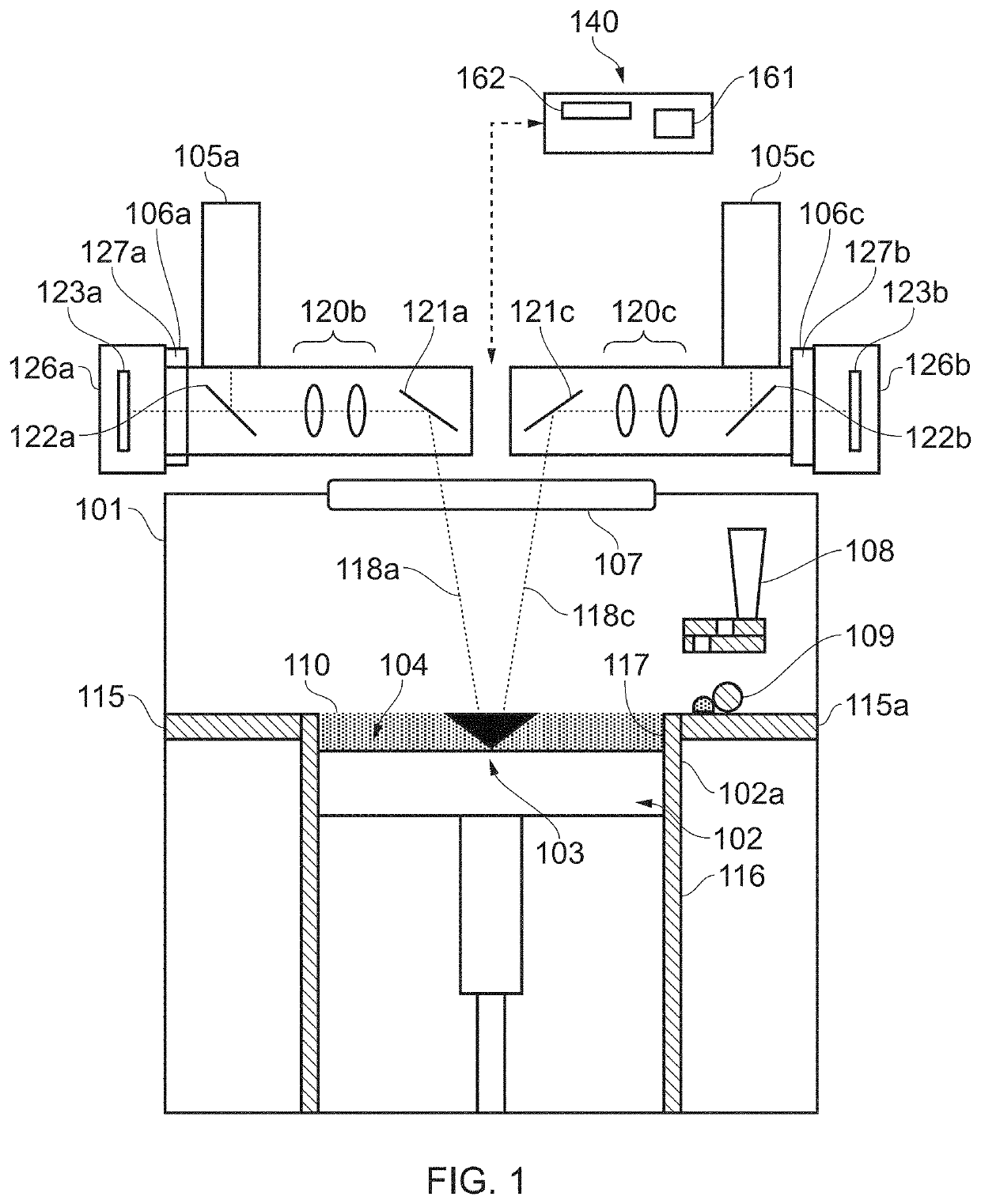
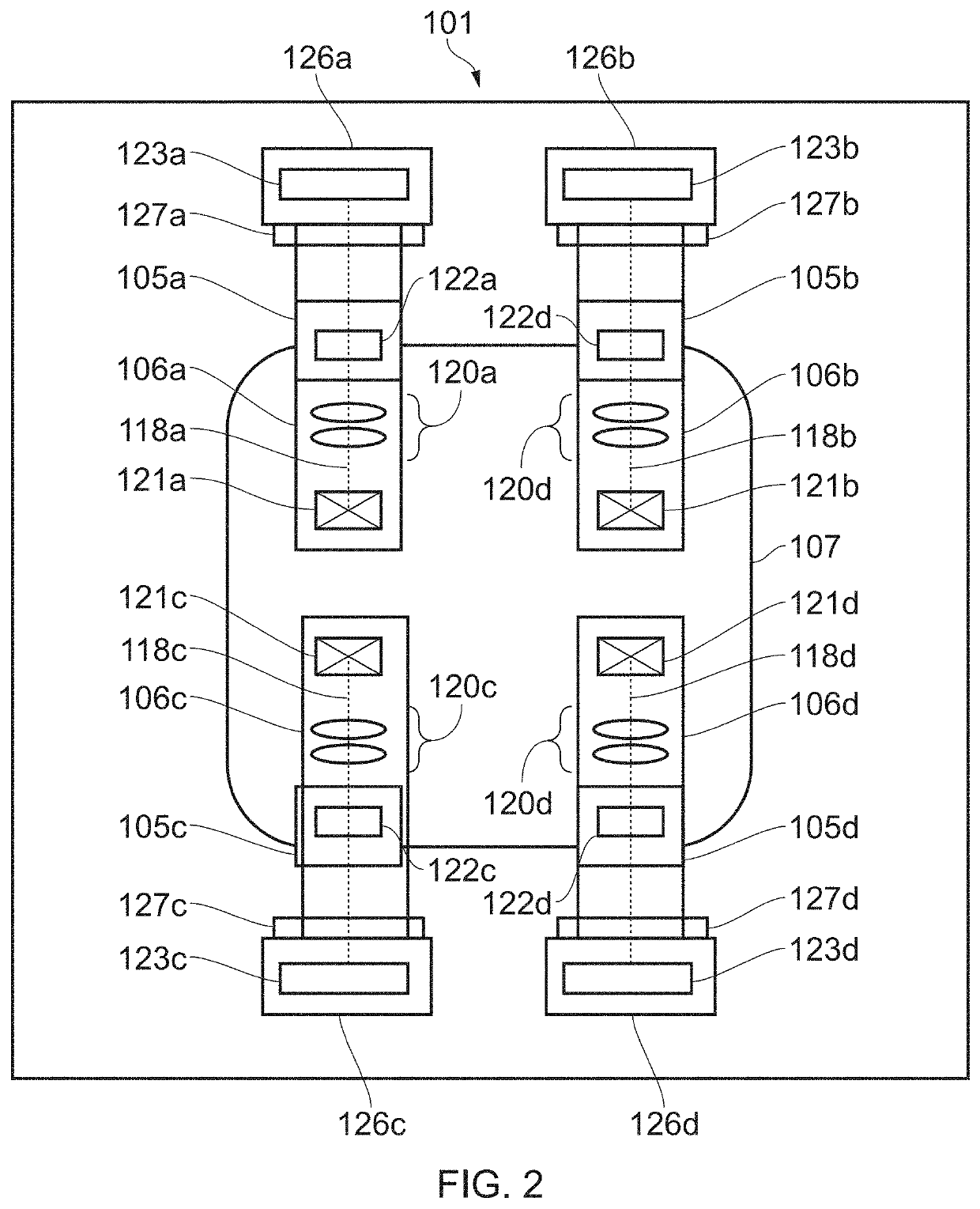
[0072]Referring to FIGS. 1 and 2, an additive manufacturing apparatus according to an embodiment of the invention comprises a build chamber 101 having therein partitions 115, 116 that define a build volume 117. A build platform 102 is lowerable in the build volume 117. The build platform 102 supports a build substrate plate 102a, a powder bed 104 and workpiece 103 as the workpiece is built by selective laser melting of the powder. The platform 102 is lowered within the build volume 117 under the control of a motor (not shown) as successive layers of the workpiece 103 are formed.

[0073]Layers of powder 104 are formed as the workpiece 103 is built by dispensing apparatus 108 and a wiper 109. For example, the dispensing apparatus 108 may be apparatus as described in WO2010 / 007396. The dispensing apparatus 108 dispenses powder onto an upper surface 115a defined by partition 115 and is spread across the powder bed by wiper 109. A position of a lower edge of the wiper 109 defines a working...


PUM

PropertyMeasurementUnit
timeaaaaaaaaaa
optical axisaaaaaaaaaa
phaseaaaaaaaaaa

Abstract

A method of aligning an on-axis melt pool sensor in an additive manufacturing apparatus. The method includes scanning a first laser beam along a first scan path across a working surface using a first optical train to generate a melt pool along the first scan path and scanning a field of view of an on-axis sensor along a second scan path across the working surface using a second optical train for steering a second laser beam. The first and second scan paths intersect. An adjustment to be made to an alignment of the field of view of the on-axis sensor with an optical axis of the second optical train is determined from a variation in the signal generated by the on-axis sensor as the field of view is scanned along the second scan path.

Description

FIELD OF INVENTION[0001]This invention concerns improvements in or relating to on axis melt pool sensors in an additive manufacturing apparatus, in particular an additive manufacturing apparatus which melts material using a laser. The invention has particular, but not exclusive, application to a laser-based powder bed fusion apparatus and more particularly, a powder bed fusion apparatus comprising multiple optical trains, each optical train for independently steering a laser beam and at least one of the optical trains comprising an on-axis melt pool sensor.BACKGROUND[0002]Powder bed fusion apparatus produce objects through layer-by-layer solidification of a material, such as a metal powder material, using a high-energy beam, such as a laser beam. A powder layer is formed across a powder bed contained in a build sleeve by lowering a build platform in the build sleeve to lower the powder bed, dosing a heap of powder adjacent to the lowered powder bed and spreading the heap of powder w...

Claims


Application Information

Patent Timeline
Patent Type & Authority Applications(United States)
IPC IPC(8): B22F10/366B22F10/28B22F12/49B22F12/45B22F12/47B22F10/85B33Y50/02B33Y30/00B33Y10/00
CPCB22F10/366B22F10/28B22F12/49B22F12/45B33Y10/00B22F10/85B33Y50/02B33Y30/00B22F12/47B23K26/032B23K26/342B29C64/153B29C64/268B29C64/393B33Y40/00Y02P10/25B22F12/44B22F12/90
Inventor DARDIS, JOHNBROWN, CERIMANSELL, JONATHAN
Owner RENISHAW PLC
Why Eureka
Try Eureka